...
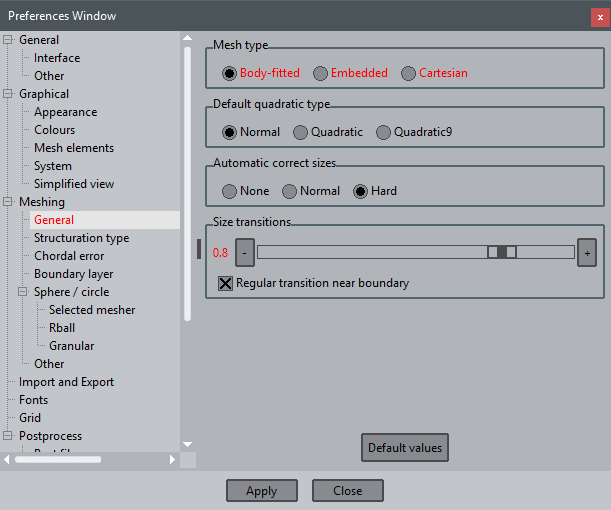
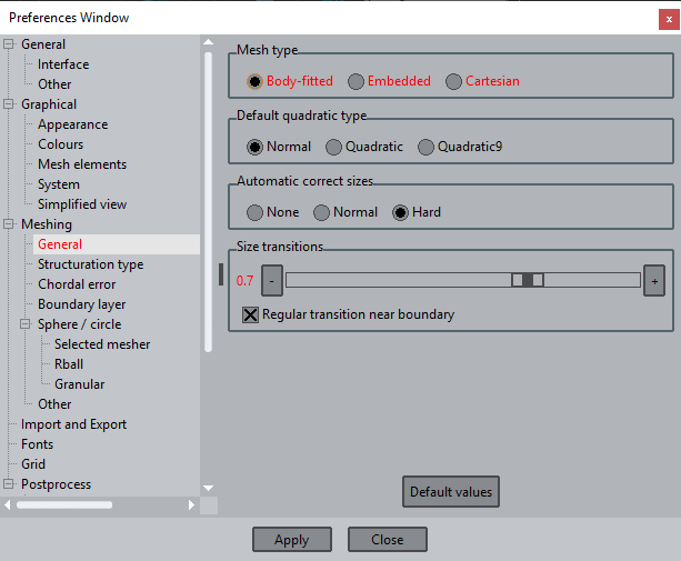
GiD user can choose between several meshing parameters to reach the final desirable mesh for the simulation. This parameters can be checked and set in the Meshing->Structuration type part of the Preferences window (see figures).
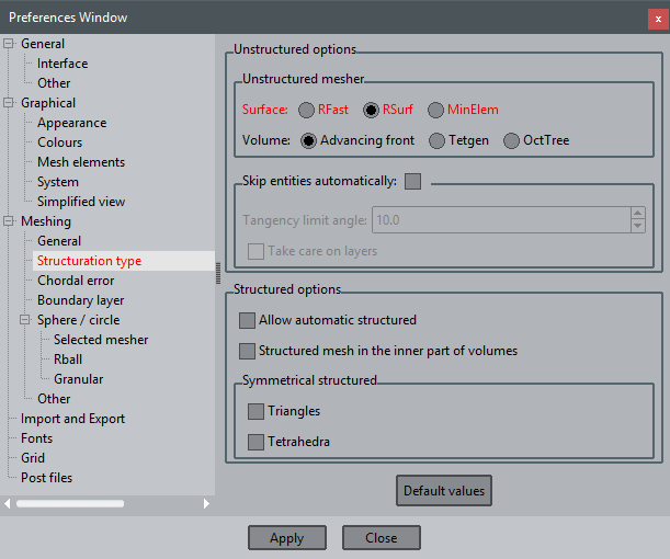
Meshing parameters used for generating the mesh in this example
...
- Surface mesher: GiD uses advancing front method for the surfaces meshing, and this method can be used in two different ways: mesh in the 2D parametric space of the corresponding surface (RFast), or mesh the surface directly in the 3D space (RSurf). The MinElem mesher is an special mesher which generates meshes with as less elements as possible, but representing accurately the shape of the geometry according to given chordal error parameters (defined in the Meshing->Chordar error branch of Preferences window). In this case we are using RSurf mesher: this mesher is slower than RFast, but usualy ensures a better quality of the resulting mesh. This aspect is specially important when the surfaces are the contour of a volume, because the success in the volume meshing depends strongly on the quality of its contour surfaces' mesh.
- Automatic correct sizes: This is a very important parameter. If this parameter is set to None, GiD will only take into account the sizes assigned by the user. This may cause some problems, specially if the assignement of sizes to the geometrical entities is not very precisely done. If the parameter is set to Normal, GiD takes into account the sizes assigned by the user, but also applies an automatic correction. This correction basically tries to avoid very aggresive mesh size changes between close geometrical entities. GiD also tries to assign a realistic size to the entities: in some cases, the user assigns a general size (or a local size to an entity) which is much bigger than the size of the entity itself. In this cases it is impossible to generate a mesh using the size specified by the user, so GiD reduces this size. If this parameter is set to Hard, besides the corrections mentioned above, GiD also tries to apply a certain chordal error criteria for assigning sizes (smaller sizes to entities with bigger curvature). We will use the Hard option.
- Unstructured sizes transition: This parameter controls how the sizes transitions are done between areas where the mesh is finer and areas where the mesh is coarser: faster (values closer to 1.0) or slower (values closer to 0.0). The bigger the parameter is, the more aggresive is the transition between small elements and big ones. The correct value for this parameter depends on the simulation requirements. Now, we will use 0.87.
- Skip entities automatically: These variables control whether a line or a point is skipped during the meshing process. Using this option, meshes can be generated with fewer elements than other ones because it is less dependent on the dimensions of geometrical surfaces. However, it is slower and can fail for distorted surface patches. We won't use this option now.
...
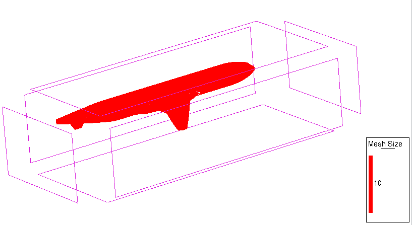
Click twice onto this message, and a big red cross will mark the problematic region of the model which made impossible the volume mesh generation (as shown in next figure).
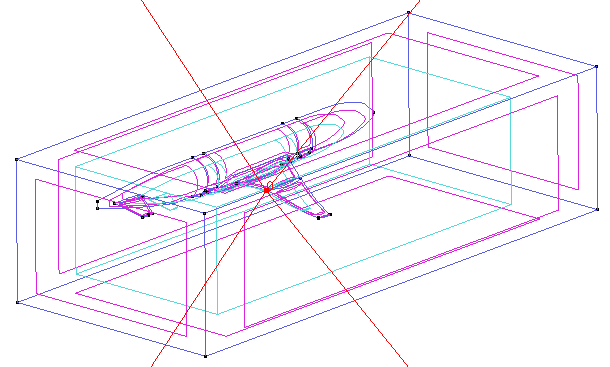
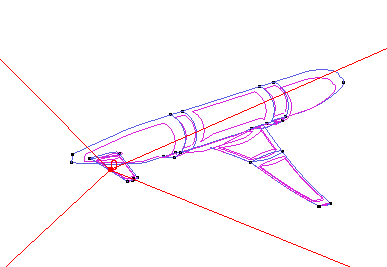
Indication of the area where the volume mesher has found some problems
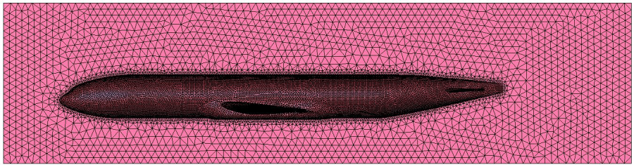
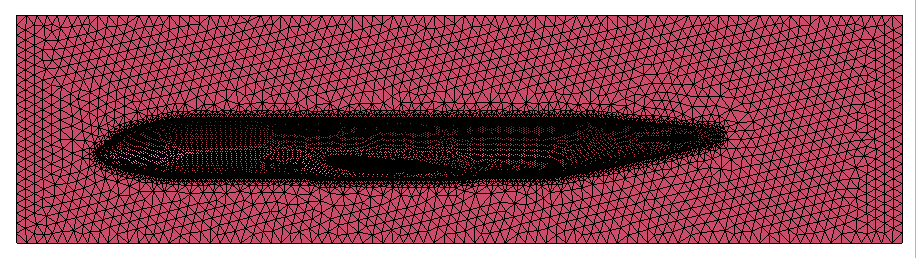
If we switch the view mode to mesh (Ctrl-m, or View->Mode->Mesh, or the corresponding icon  in the toolbar) and zoom in the problematic area, it can be seen that there are triangles very big in comparison to the ones in the edge of the wing (next figure). This may be the problem for meshing the volume.
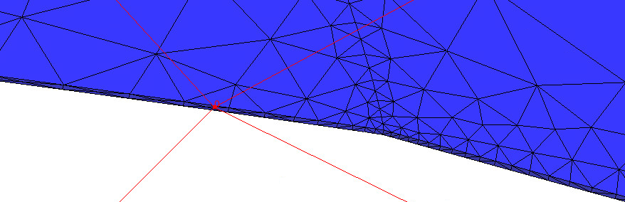
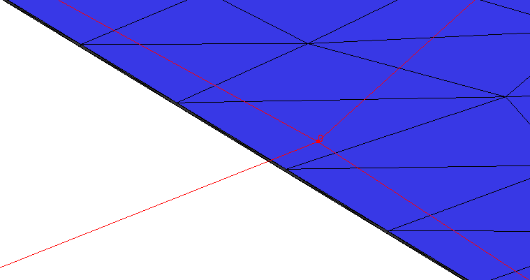
Zoomming in the problematic area signaled by the Mesh error window, in Mesh view mode.
Note: Depending on the GiD version and meshing parameters maybe the problematic point is another, or maybe it is possible to generate a volume mesh, then ignore these last steps.
...
Local size assignment
One possible solution for this problem may be to mesh the whole model with a size similar to the one of the edge of the wing, but this will generate a big amount of elements, and it should be taken into account that this small size may not necessarily improve the accuracy of the simulation.
We are going to assign different sizes to the surfaces of the aircraft, the surfaces of the control volume, and the volume itself.
...
Note that using this procedure user can assign different sizes to any kind of geometrical entity.Now generate the mesh again (Ctrl-g or Mesh->Generate mesh). The mesh can not be generated again, and we see that GiD shows another part of the wing again as a problematic area. Depending on the GiD version the problematic area may be different, for instance in the tail wing.
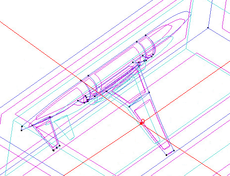
Another problematic area for the volume mesh generator.
Local size assignment
We will assign a smaller size to the surfaces of the end part of the wings. These surfaces are the number 7, 12 and 24. The id of surfaces can be checked using the Label option in the right mouse button menu. When the option Label->Surfaces is selected user can select the surfaces (with the mouse) which wants to know its number, or write down in the command line (lower part of the window) the numbers of the surfaces to be selected.
- Select Mesh->Unstructured->Assign sizes on surfaces. Enter 3 and select those surfaces (7, 12 and 24). Then press ESC.
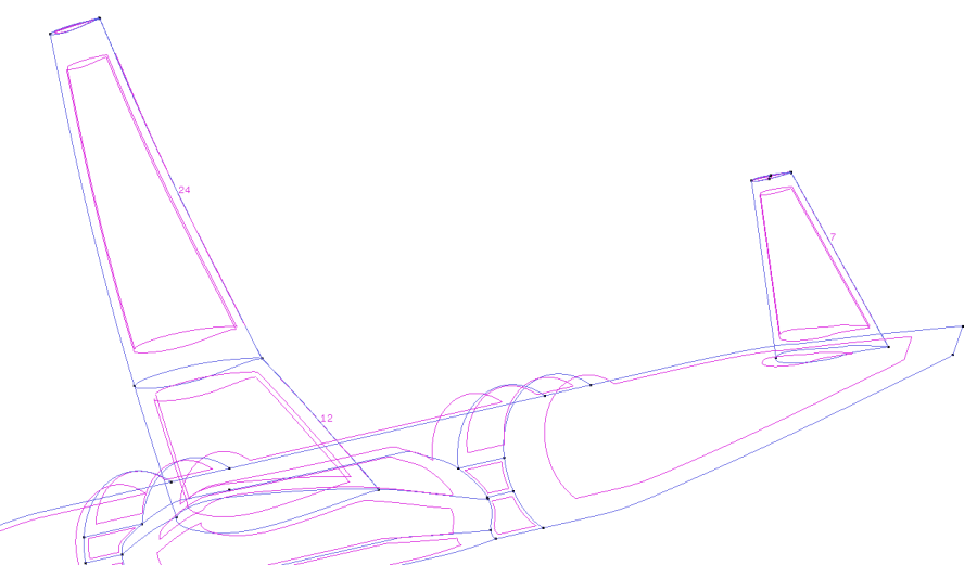
Surfaces to assign mesh sizes with label on
GiD offers many graphical tools to check which meshing properties are assigned to the geometry (size, element type, GiD offers many graphical tools to check which meshing properties are assigned to the geometry (size, element type, etc.). This options are accessible from Mesh->Draw options. You can check the sizes assigned to the surfaces by selecting Mesh->Draw->Sizes->Surfaces:
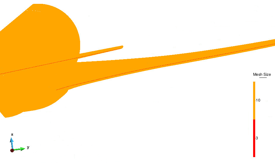
The red line color corresponds to the surfaces with small size assigned.
You can try now to Now generate the mesh as before again (Ctrl-g or Mesh->Generate mesh), and and you will see that with these sizes assigned the volume mesh can be generated.
Final mesh