GiD - The personal pre and post processor
Geometry importation and CAD cleaning operations
Description
This course is focused on the geometry importation and cad cleaning operations which are needed in most cases for prepare the imported model to be meshed
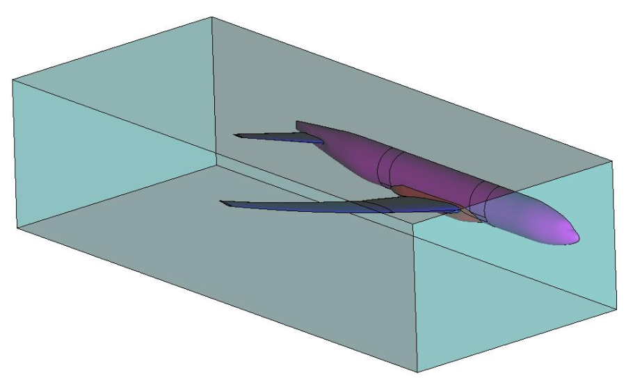
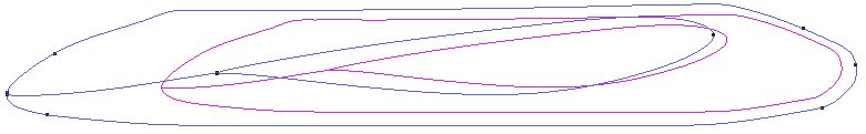
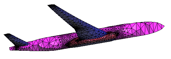
Final model obtained when following all the steps of the course.
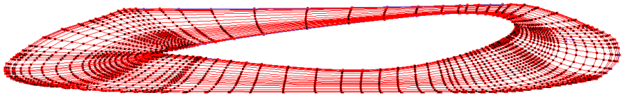
We will import the geometry of half an aircraft (shown in the figure) in IGES format and we are going to follow the whole process from the importation to the meshing process of a control volume surrounding the aircraft.
Note: the model originally was a "NASA Common Research Model" (commonresearchmodel.larc.nasa.gov)
Import of the model
GiD import and export preferences
The user can customize some parameters for the import and export of geometry. This parameters are located in the Import and Export part of Preferences window.
- Click on Utilities->Preferences and go to the Import and Export part. The window shown in figure should appear.
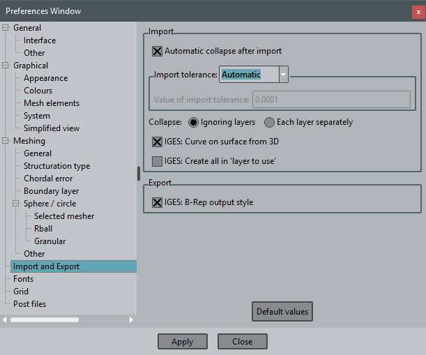
Import and Export preferences window.
When GiD imports a geometry (independently on the format), it automatically perform some cad cleaning and repairing operations such as check entities orientations, collapse small gaps, etc. User can avoid this automatic operations by unchecking the Automatic collapse after import.
If the automatic collapse is set, GiD can use a distance tolerance entered by the user, or can compute an automatic tolerance based on the representative size of the model. With the option Automatic import tolerance value user can choose whether the tolerance is automatic or the manually specified.
We are going to set all the options shown in the figure and click Apply.
Import model
The IGES file to be imported is named half_aircraft.igs and it should be found at Material location. .
- Select Files->Import->IGES... and select the file half_aircraft.igs.
A progress bar appears showing the state of the automatic CAD cleaning operations GiD does when imports the IGES file.
On the lower messages bar you could see the tolerance used for the automatic collapse operations, and the result of the automatic collapse on import.
Import tolerances
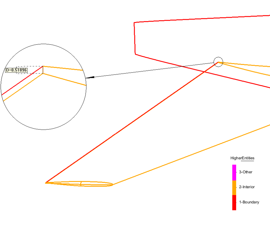
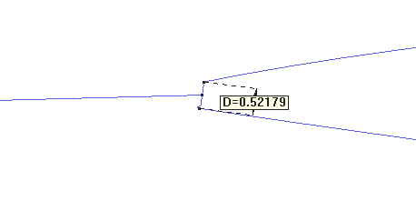
After importing a model with automatic tolerances, it is very useful to check how the model looks like, and get a minimum characteristic distance, to ensure the automatic tolerance computed by GiD does not collapse any geometric detail interesting for simulation. In this case, it should be useful to measure the distance of the ending part of the tail, as it is shown in figure.
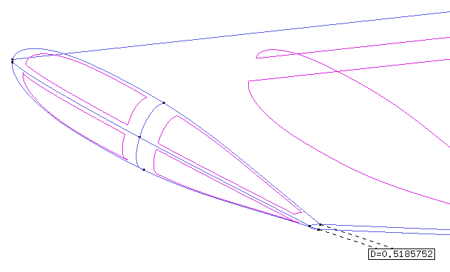
Size of the end part of the tail.
You can check it by using Utilities ->Dimension ->Create ->Distance, selecting the two points and placing the dimension label.
As it can be seen in the preferences window, now the automatic tolerance for the collapse computed by GiD is 0.126698.
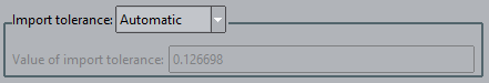
Depending on the version of GiD used, this tolerance can be different, so the result of the import of the model may differ in some details.
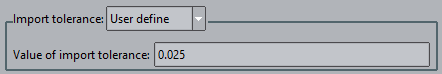
To ensure that all the participants of the course have the same model resulting from the import, we will use a tolerance specified by the user. Taking into account the distance shown in the previous figure, we can try for example with an Import tolerance of 0.025 that is smaller than the detail to preserve. For this purpose we need to import again the model:
- Select Files->New, and select No for the question Save changes to this project.
- Open the Preferences window, and go to the Import and Export part.
- Select from the combobox Import tolerance: Used define
- Enter 0.025 in the Value of import tolerance field.
- Click on Apply and close the Preferences window.
Now import again the IGES file half_aircraft.igs (Files->Import->IGES...).
Once the model is imported, save the model (this will be the model we will work with during this course). For saving the model just select Files->Save and choose a proper location in your computer to save the model in.
CAD cleaning operations
Visual check of geometry
A useful step when a file is imported is to check visually how it looks like. Rotate the model and set the Render mode to Flat (from the View menu or mouse right button menu). With this initial visual scan some possible big geometry imperfections or import errors may be detected.
If some surface is not well rendered (like strange shadows or holes in the view) or no render is done, it means that GiD had some problem to generate the render mesh of the surface. This should point a possible error in that surface (or may be not).
Trick: the GiD-Tcl procedure GiD_Geometry list -unrendered surface provides the list of surfaces that were not able to be rendered.
You can write this in the command line to know this list:
-np- W [GiD_Geometry list -unrendered surface]
A message window will appear, but in this case it is empty, as all surfaces were rendered.
As it can be seen in the figure, the render of the surface which connects the wing of the aircraft with the main fuselage looks a bit off.
Render view of the model imported, with the surface which render is not so good highlighted.
Let's check if this surface is well defined or not. A good idea is to isolate this surface in another layer to visualize it more clearly.
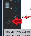
- Open the Layer window ( Ctrl-l , (lower L) or Utilities->Layers and groups, or the corresponding icon
 in the Toolbar)
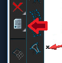
 - Create a new Layer (using the New Layer option in the mouse right button menu, or using the corresponding icon in the upper icon bar of the Layers window).
- Send the surface to the new layer by using the Sent to->Surfaces option of the mouse right button menu after the target layer is selected (the corresponding icon in the upper part of Layers window can be also used).
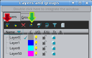
'New layer' and 'Send to' icons.
Now we can switch off all the layers except the one in which the surface is. We should be able to see just this surface, as shown in the figure.
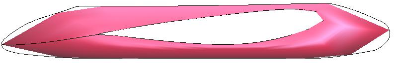
View of the problematic surface isolated.
We can change the render mode between Normal and Flat to understand better the definition of the surface:
'Render normal' view
Generate automatic test mesh
Another useful check that can be done when importing the geometry is to generate a first mesh, using the default meshing preferences of GiD. Often, some detail of the model which can be skipped during the visual scan is detected when looking at the mesh, for instance, possible concentration of elements, entities which cannot be meshed, etc.
- Open the Preferences window select Meshing and with right mouse click select Default values on selection from the pop-ip menu, ensure that Also selection children is checked, and press Apply.
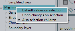
Set default values to selection and its chidren
- Then generate the mesh by pressing Ctrl-g or by selecting Mesh->Generate mesh... and click OK using a mesh size of 140 and unchecking the Get meshing parameters from model option:
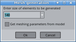
General mesh size window
As it can be seen in the figure GiD can generate a mesh on all the surfaces.
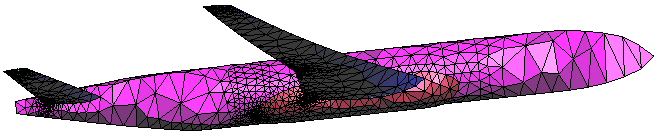
Coarse mesh
In this step is not important to check the mesh quality, but to check where the elements are concentrated, and if there are surfaces which cannot be meshed.
Looking for gaps
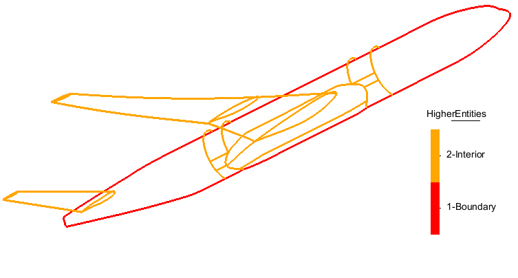
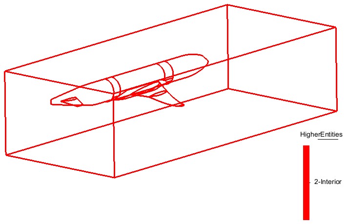
One of the typical problems when importing geometry is to have small gaps or overlapped surfaces in a model where they should not appear. An easy way of checking the topology of the model using GiD is to see graphically the higher entity number of the geometrical entities. The higher entity number of an entity represents the number of entities (with one more dimension) containing itself (for a given line, for example, the higher entity number represents the number of surfaces owning this line).
In this case, for example, as we need the geometry of the aircraft to be a boundary of a volume (the air surrounding the aircraft), we need it to be water-tight. This implies that all the inner lines of the aircraft should have higher entity number equal to 2.
- Return to geometry mode, if you are on mesh mode, by clicking at View->Mode->Geometry, or the switch mode icon
Toolbar button to switch geometry<->mesh view
- Select View->Higher entities->Lines.
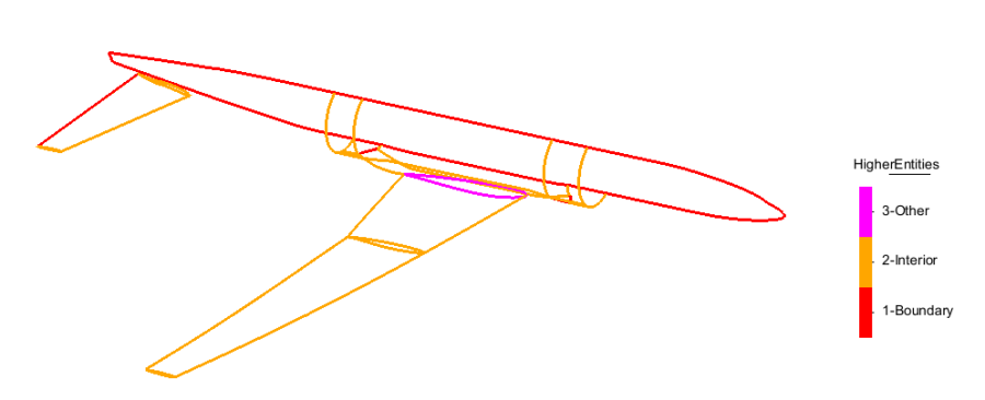
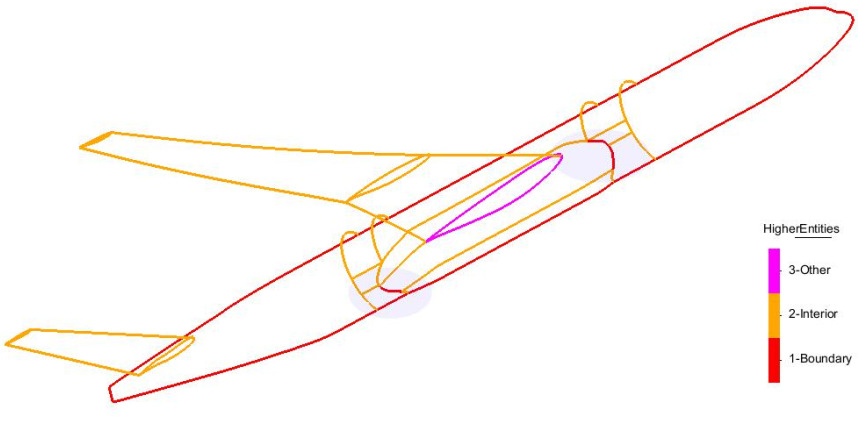
Higher entities of lines in the model
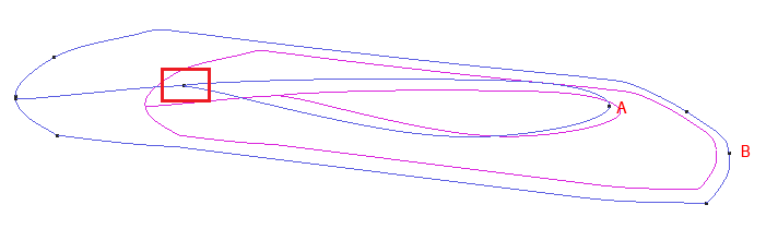
As it can be seen in the previous figure, there are some inner lines with higher entity number equal to 3, and some other with higher entity number equal to 1. These last ones evidence the presence of some gap in the geometry.
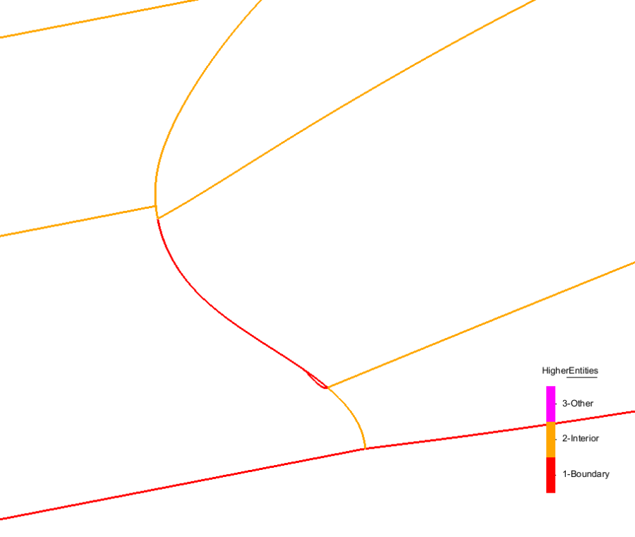
We will study in more detail the gap of the tail (the red lines that belong to only 1 surface instead 2 as expected).
Gaps with duplicated overlapped lines.
You can check it with Utilities ->Distance or Utilities ->Dimension ->Create →Distance
If we list the entities with Utilities->List->Lines or the corresponding icon:
Selecting a square on the red line, we obtain that there are two lines.
Collapse model
Taking into account that the measured distance on the tail is about 0.5 units, we can try to collapse the whole model with a higher tolerance than the used in the import process (remember that was 0.025), for instance, a 10% of the measured distance, to join entities closer that this value.
- Open the Preferences window, go to the Import and Export part, and change the Value of import tolerance to 0.05.
- Click on Apply button and then you can close the Preferences window.
Note: This import tolerance is used both when importing a model, and when collapsing entities of a model already inside GiD.
- Select Geometry->Edit->Collapse->model and click OK on the appearing window to allow the operation of collapsing the model.
A message in the lower messages bar show this:
Collapse model. Created -1 points, -3 lines, 0 surfaces, 0 volumes. Tolerance=0.05
This mean that one point and three lines closer than 0.05 units were deleted.
As you can see if you view again the higher entities of lines, now the gap in the rear part of the aircraft has disappeared. Now we only have the two gaps of the figure.
Higher entities of lines
Local collapsing
To try to repair the gaps which remains in the model, one option should be to increase more the tolerance and try to collapse again the model, but the tolerance is approaching the measured minimum characteristic size of the model, and some important details, such as the ending part of the wings, would be collapsed too, and this could be undesirable.
We are going to collapse the lines enclosing the gaps with a higher tolerance, but only these lines (not the whole model).
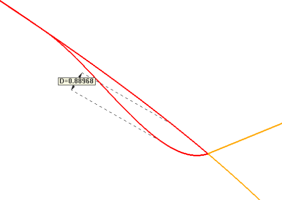
In the Figure it can be seen the configuration of the lines before the local collapsing.
It is possible to measure the distance between both lines with Utilities->Distance and selecting in the contextual mouse menu the Point In Line option and picking two points on the lines. This distance is about 1.0 units, to force a join between these two lines, it is necessary to set a bigger value as import tolerance.
|
|
- Set the value of import tolerance on the Import and Export part of Preferences window to 1.1, and click Apply before closing the window.
- Select Geometry->Edit->Collapse->Lines and select the two lines which surround one of the gaps (the lines with higher entity equal to 1).
- Repeat this action on the other gaps of the model, but only selecting the wrong lines.
Once finished with this local collapses, in the Import and export child of the Preferences window set the Import tolerance to Automatic, to avoid deleting parts accidentally when collapsing with a too big tolerance.
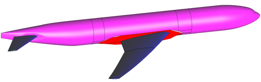
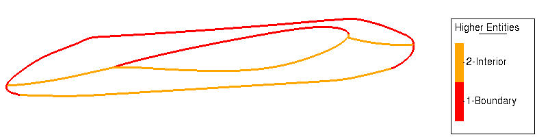
Now, if you try to see the higher entities of lines, only the boundary lines of the half-aircraft should have higher entity number equal to 1. We can see also some lines with Higher entity number equal to 3. This indicates that these lines are owned by three surfaces. In this case, there is no error in the geometry, but we can delete the inner surface which connects the wing with the fuselage (see figure below), because it is not of interest for the process we want to do.
- Geometry->Delete->Surfaces
Surface to be deleted because it is not of interest for the simulation
In next figure it is shown the higher entities of lines after all the cleaning operations performed until now: you can see all the lines have higher entity equal to 2, except the lines of the boundary of the half-aircraft.
Higher entities of lines after the local collapsing and after deleting the unnecessary surface
NURBS simplifying
The surface number 13 has a lot of control points for its geometrical definition. This surface is the problematic surface shown at the begining of this document.
If we list this entity with Utilities->List->Surfaces it take a long time to show this information window:
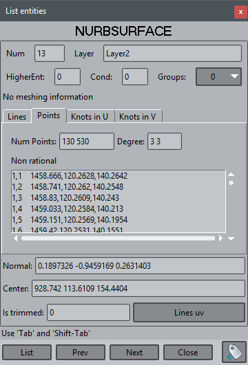
Geometrical information of NURBS surface
We can see that its control polygon has 130 x 530 = 68,900 control points. This situation will lead to a very heavy model in terms of amount of memory used to deal with it, and often this NURBS definition can be simplified without loosing accuracy for capturing the shape of the surface.
To do it open Geometry->Edit->Edit NURBS->Surface... and pick the surface:
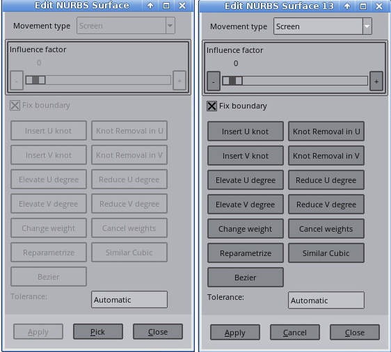
Edit NURBS window, before (left) and after (right) selecting a NURBS surface.
- When the control points are visible (after clicking Pick in the Edit NURBS surface window and selecting the surface), click on the option Knot removal in U. You can see that the number of control points have decreased, and in the warn line (lower part of GiD window) a message shows the memory reduction needed to store the surface.
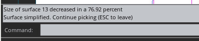
- Click on the options Knot removal in U and Knot removal in V as many times as needed, until the message in the warn line indicates that the surface is not simplified any more (decreased in a 0.00 percent).
- Click on Apply to accept the NURBS simplification and Close the window.
As it can be seen in next figure, now the surface is defined with much less control points than the original one, and now it is easier to check how the control points distribution looks like.
Control points of the surface once it is simplified
Listing the surface again we can see that its new control polygon has 24 x 117 = 2,808 control points. These numbers are indicative as they depend on the order of execution of the Knot removal in U and Knot removal in V operations.
Problematic surface
Also after the simplification the render mesh of the surface 13 is not very good. There are two main difficulties for the meshing algorithm of the surface:
1. There are small lines related to the mesh size (the border of the wing has about 0.5 units, and the general mesh size asked was 140 units)
The red square shows the zoomed area at the read border of the wing.
To avoid having small elements the geometry could be modified, collapsing with a size greater to 0.5 to delete the very thin surface of the back of the wing, and convert it in a single line. Then the mesh could have much less elements, but maybe the shape of this part is important for the simulation and must not be changed.
2. The surface is 'closed' because it is topologically like a ring. The parametric surface curves v = 0 and v = 1 when mapped by the parametric surface become the same 3D curve, and the inverse of this parametrization is not unique (a 3D point could be mapped in two different parametric space points).
We will try to aid the mesher by dividing the surface in two parts in the middle of the v parametric direction.
To do so:
- Use the tool Geometry->Edit->Divide->Surfaces->Num. divisions
- Select the surface, click on V sense and enter 2 on number of divisions, Ok
After this division they appear some extra problem of higherentities connecting the new surfaces with the rest of the model.
Higher entities of lines
To fix the problems, switch all layers on, use the collapse lines tool locally again, and increase the tolerance as necessary to join the similar lines.
Let's mesh the model:
Coarse surface mesh
Create volume
We are going to create the control volume surrounding the half-aircraft in this section. This control volume will represent the air surrounding the aircraft.
For this purpose, using the Line creation tool  , create the rectangle with vertex in the points:
-220,0,745
-220,0,-155
3280,0,-155
3280,0,745
Note: Remember to use Ctrl + a to select the last existing point to close the rectangle.
Then create a surface with this created lines as their contour lines:
- Select Geometry->Create->NURBS surface->By contour, and select these last created lines.
At this point, the geometrical model should look like the one shown in the figure.
State of the model at this point
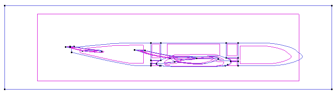
Now we should create a hole in the new rectangle, so as the inner boundary of this surface will be the contour of the half-aircraft (the lines which have higher entity equal to 1 previously).
- Select Geometry->Edit->Hole surface->With lines and select the rectangular surface created previously.
- Then select the contour lines of the half-aircraft and press ESC.
Trick: To select the contour lines of the half-aircraft, you can use the Selection window, by selecting this option from the contextual right mouse menu.
By doing that is really easy to select all lines with higher entity 1, press apply, and unselect just the 4 lines of the rectangle:
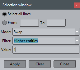
Selection window
A hole in the rectangular surface should be created, like it is shown in the figure.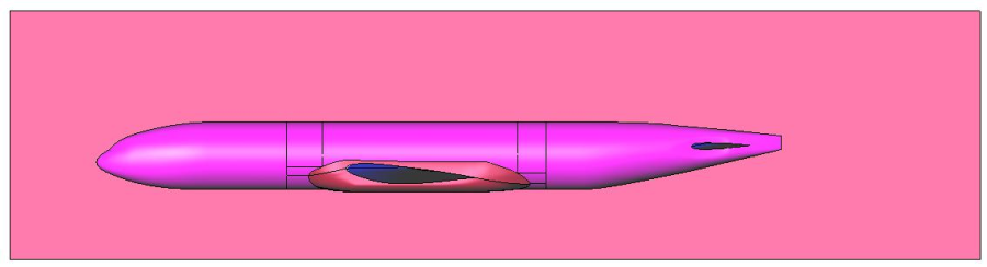
Rectangle holed with the lines of the plane
The hole created in the rectangular surface, using the boundary lines of the half-aircraft.
Now we are going to extrude the outer lines of the rectangle to build the control volume:
- Open the Copy window (Utilities->Copy or use Ctrl-C (capital C)) and set the options shown in the figure:
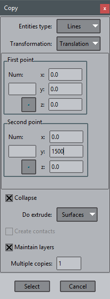
Options to be set for the extrusion of the lines
- Click on Select, select the four lines of the rectangle created previously, and press ESC. Press Cancel to close Copy window.
Now the next step is to create the surface which will close the control volume.
- Create the surface with Geometry->Create->NURBS surface->Search
- and click one of its four boundary lines. This tool will try to automatically find and create a surface that has this line in its boundary.
If you look at the higher entities of lines of the resulting model you should obtain that all the lines have higher entity equal to 2, which means that the patch of surfaces of the model can close a volume topologically.
View of higher entities of lines at this point
The last step is to create the volume:
- Select Geometry->Create->Volume->By contour, and select all the surfaces of the model. Then press ESC.
Now we have finished the geometrical definition of the model, and we should have at this point the model shown in the figure (where the created volume is shown with sky-blue lines).
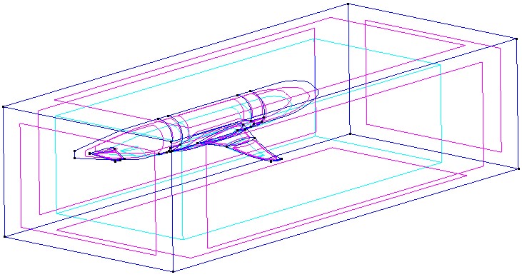
The geometrical model after all the import operations and the control volume creation
Generate final mesh
We are going to go deeper in the mesh generation process in this part. The CAD cleaning operations can be understood as all the operations needed from the moment of importing the model to the moment of runing the simulation itself. This implies to have a CAD model from which the preprocessor can generate a mesh suitable to be used in the simulation.
In this point we can establish that the geometry cleaning part has ended, and we are going to explore some of the possibilities GiD offers in the mesh properties assignment, to be able to generate the mesh.
Meshing parameters
Be sure than Meshing->General has Body-fitted mesh type.
GiD user can choose between several meshing parameters to reach the final desirable mesh for the simulation. This parameters can be checked and set in the Meshing->Structuration type part of the Preferences window (see figures).
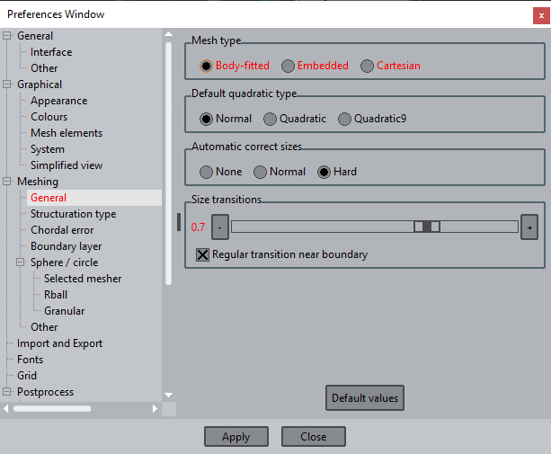
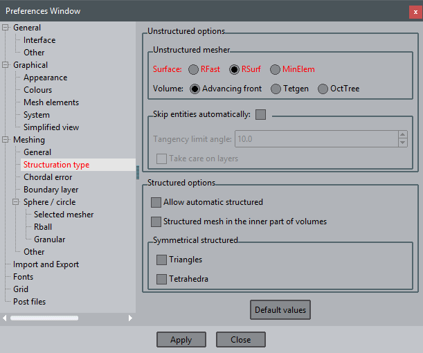
Meshing parameters used for generating the mesh in this example
Please, set all the parameters as the ones shown in the above figures, and click Apply.
In the GiD Help all these variables are explained in detail. We will focus in some of them in this part, just to justify why we are usingthis ones and not others.
In the Meshing->General branch:
- Mesh type: Body-fitted is the usual kind of mesh, the mesh preserves the shape of the geometry. The other alternatives are for special solvers.
In the Meshing->Structuration type branch:
- Surface mesher: GiD uses advancing front method for the surfaces meshing, and this method can be used in two different ways: mesh in the 2D parametric space of the corresponding surface (RFast), or mesh the surface directly in the 3D space (RSurf). The MinElem mesher is an special mesher which generates meshes with as less elements as possible, but representing accurately the shape of the geometry according to given chordal error parameters (defined in the Meshing->Chordar error branch of Preferences window). In this case we are using RSurf mesher: this mesher is slower than RFast, but usualy ensures a better quality of the resulting mesh. This aspect is specially important when the surfaces are the contour of a volume, because the success in the volume meshing depends strongly on the quality of its contour surfaces' mesh.
- Automatic correct sizes: This is a very important parameter. If this parameter is set to None, GiD will only take into account the sizes assigned by the user. This may cause some problems, specially if the assignement of sizes to the geometrical entities is not very precisely done. If the parameter is set to Normal, GiD takes into account the sizes assigned by the user, but also applies an automatic correction. This correction basically tries to avoid very aggresive mesh size changes between close geometrical entities. GiD also tries to assign a realistic size to the entities: in some cases, the user assigns a general size (or a local size to an entity) which is much bigger than the size of the entity itself. In this cases it is impossible to generate a mesh using the size specified by the user, so GiD reduces this size. If this parameter is set to Hard, besides the corrections mentioned above, GiD also tries to apply a certain chordal error criteria for assigning sizes (smaller sizes to entities with bigger curvature). We will use the Hard option.
- Unstructured sizes transition: This parameter controls how the sizes transitions are done between areas where the mesh is finer and areas where the mesh is coarser: faster (values closer to 1.0) or slower (values closer to 0.0). The bigger the parameter is, the more aggresive is the transition between small elements and big ones. The correct value for this parameter depends on the simulation requirements. Now, we will use 0.7.
- Skip entities automatically: These variables control whether a line or a point is skipped during the meshing process. Using this option, meshes can be generated with fewer elements than other ones because it is less dependent on the dimensions of geometrical surfaces. However, it is slower and can fail for distorted surface patches. We won't use this option now.
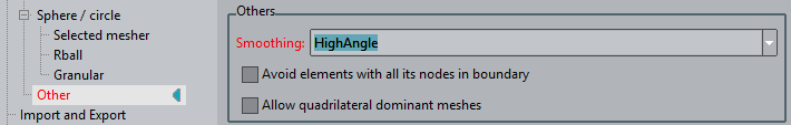
Smoothing: HighAngle
In the Meshing->Other branch:
- Smoothing: This parameter can be set to three different values: Normal, HighAngle, HighGeom. The Normal option performs a regular smoothing to the mesh generated. The HighAngle option focuses on improving the shape of mesh elements. HighGeom tries to make the final mesh closer to the geometry, performing topological operations in order to minimize the chordal error of the elements. This last option reduces the chordal error, but has an affect on the quality of the shape of the elements. For this example we will use the HighAngle option.
Set the Smoothing to HighAngle.
First attempt in mesh generation
As it can be seen in previous figures, the default size used in the mesh generated by GiD is too coarse for any kind of simulation. With the general mesh size, provided at the moment of generating the mesh, the user has few control to generate non uniform meshes. By the way, we are going to try a first mesh generation just reducing the general mesh size.
After the mesh generation, we are going to tell GiD to give (after the mesh generation process) not only the generated tetrahedra, but also the triangles of the surfaces (by default, only the higher dimension elements are given). This is useful when the volume mesh could not be generated, thus allowing us to take a look on the mesh of its contour surfaces. Many times, the problem of generating a volume mesh are directly related to the bad-quality of the surfaces' mesh.
For this purpose:
- Select Mesh->Mesh criteria->Mesh->Surfaces, and select all the surfaces of the model. Then press ESC.
GiD has several meshing algorimths, if the selected one fails for some entity another algorithm is used.
It is possible to change this behaviour with the GiD variable OnlyUseSelectedMesherVolumes or OnlyUseSelectedMesherSurfaces.
If you write this in the Command line:
Mescape Utilities Variables OnlyUseSelectedMesherVolumes 1 Mescape
Then, we will detect if the advacing front volume mesher fails (otherwise the volume mesh may be generated using the Tetgen Delaunay mesher, with less element quality).
Now generate the mesh:
- Pres Ctrl-g or select Mesh->Generate mesh, erase the old mesh when asked, and enter 40 as the general meshing size and click OK. (This step may last some minutes).
After the mesh generation, a message appears telling that the mesh of the volume 1 cannot be generated ('Couldn't mesh at this location).
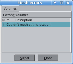
Mesh errors window
Click twice onto this message, and a big red cross will mark the problematic region of the model which made impossible the volume mesh generation (as shown in next figure).
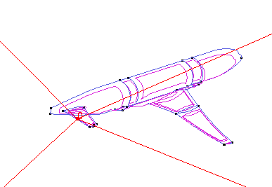
Indication of the area where the volume mesher has found some problems
If we switch the view mode to mesh (Ctrl-m, or View->Mode->Mesh, or the corresponding icon  in the toolbar) and zoom in the problematic area, it can be seen that there are triangles very big in comparison to the ones in the edge of the wing (next figure). This may be the problem for meshing the volume.
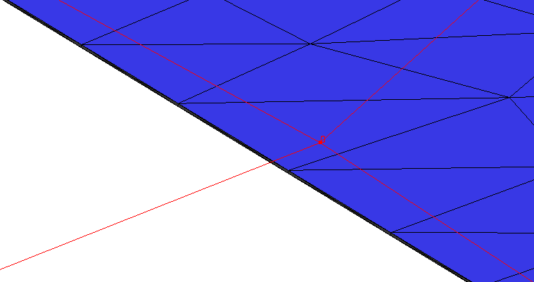
Zoomming in the problematic area signaled by the Mesh error window, in Mesh view mode.
Note: Depending on the GiD version and meshing parameters maybe the problematic point is another, or maybe it is possible to generate a volume mesh, then ignore these last steps.
Local size assignment
One possible solution for this problem may be to mesh the whole model with a size similar to the one of the edge of the wing, but this will generate a big amount of elements, and it should be taken into account that this small size may not necessarily improve the accuracy of the simulation.
We are going to assign different sizes to the surfaces of the aircraft, the surfaces of the control volume, and the volume itself.
- Select Mesh->Unstructured->Assign sizes on surfaces. Enter 10 and Assign it to all the surfaces of the half-aircraft. Then press ESC.
- Click on Close to close the surface sizes assignment window.
Note that using this procedure user can assign different sizes to any kind of geometrical entity.
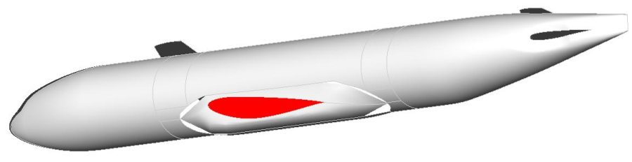
GiD offers many graphical tools to check which meshing properties are assigned to the geometry (size, element type, etc.). This options are accessible from Mesh->Draw options. You can check the sizes assigned to the surfaces by selecting Mesh->Draw->Sizes->Surfaces:
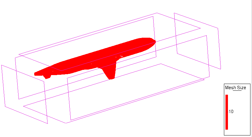
The red color corresponds to the surfaces with small size assigned.
Now generate the mesh again (Ctrl-g or Mesh->Generate mesh) and you will see that with these sizes assigned the volume mesh can be generated.
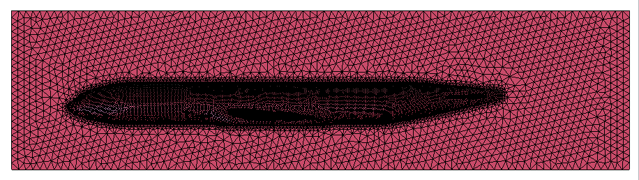
Final mesh
COPYRIGHT © 2022 · GID · CIMNE