This course is focused in the basic meshing features and capabilities of GiD.
To follow this course, the models gid_model_basic_meshing_course.gid and gid_embedded_example.gid must be loaded from the folder where the courses material is.
...
GiD offers two options to force the structured direction of a semi-structured volume: set the structured direction via a line following that direction (the option just done before), or set one of the tops of the prism ('Mesh->Semi-structured->Set->Master surface').
Cartesian mesh
To generate a Cartesian mesh of the model, set this mesh type in the Meshing→General branch of the preferences window. Once this option is selected, the 'Cartesian' branch appears in the Meshing part of the Preferences window.
We will leave all the default values and generate the mesh with a size of 0.5.
View of the cartesian mesh of the model generated with size 0.5.
It can be seen (in the Meshing→Cartesian branch of preferences window) that the default Cartesian mesher of GiD (Scan convert) is only generating volume elements. To generate line or surface elements, the mesher 'Zmesher' can be used.
Embedded mesh
For this section, we will work with the model gid_embedded_example.gid (it can be loaded from the folder where the courses material is). This model have a cubic volume, and the skin surface of a sphere.
As explained before, an embedded model consists in some volumes (the calculation volumes), and embedded regions defined by collection of surfaces. In this case, the calculation volume is the cube, and the embedded region is defined with the sphere surfaces.
First of all, select the 'Embedded' mesh type in the Meshing→general branch of the preferences window.
Then, generate the mesh of the model (Mesh→generate), using a general mesh size of 1. The following mesh should be generated:
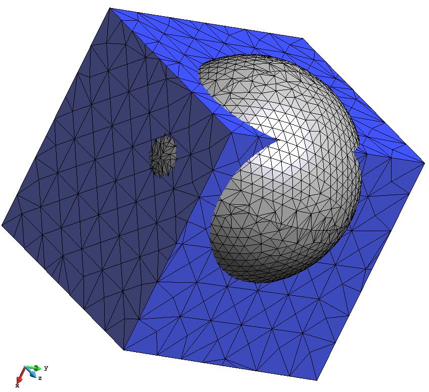
View of the mesh generated.
As an embedded mesh, it can be seen that the volume mesh is fitted to the calculation volume (cube), and it is not conformal nor body-fitted to the embedded region (sphere skin).
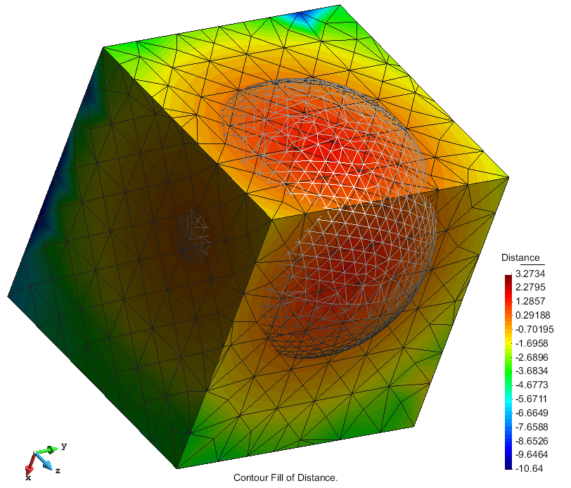
A field of signed distances to the embedded contours has been calculated on the nodes of the calculation volume mesh. They are stored with the model, and can be appreciated going to the post-processing part of GiD (where they are loaded as a result), and visualizing the contour fill of it, or some iso-surface (for instance).
...
...
...
Element types
For this section we need to load the model gid_model_basic_meshing_course.gid
The different element types GiD can generate are the following ones:
- Surface: triangle, quadrilateral, circle
- Volume: tetrahedra, hexahedra, prism, spheres and points.
There are some limitations in terms of element types permitted depending on the mesh type:
- hexahedra and prism elements can only be generated in structured or semi-structured volumes.
- Embedded meshes are only implemented for tetrahedra volume elements
- Cartesian meshes only generate hexahedra (for volumes), quadrilateral (for surfaces) and line (for lines) elements.
Considering this, selecting an element type is as easy as going to the 'Mesh' menu, setting the 'Element type' and select the desired entities.
In order to see different types of elements on this model follow this steps:
- Reset previous mesh data (Mesh->Reset mesh data).
- Set as structured volume number 4, with 5 divisions in its contour lines.
- Set as semi-structured volume number 5 with 5 structured divisions.
- Set Hexahedra as element type for volume number 4.
- Set 'Sphere' as element type of the spherical volume (volume number 3).
- Set 'Quadrilateral' as element type of surface number 18.
To check graphically the element types (or other meshing properties) assigned to the model, the 'Draw' option in the 'Mesh' menu is useful.
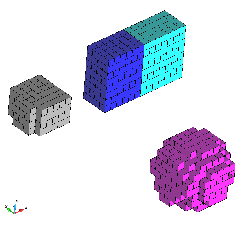
- Select Draw->Element type->Volumes in order to check the element types assigned. The result should be like the following image:
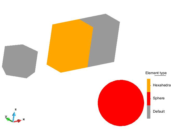
Different element types assigned to the model volumes shown using the Mesh->Draw option.
- Generate the mesh. The resulting mesh should be like the one shown in the following figure:
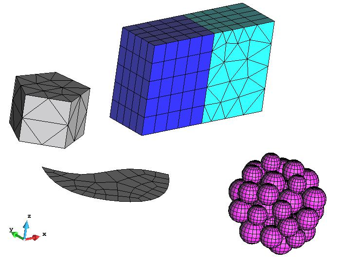
View of the mesh generated with the different element types assigned.
...
Element types
The different element types GiD can generate are the following ones:
- Surface: triangle, quadrilateral, circle
- Volume: tetrahedra, hexahedra, prism, spheres and points.
There are some limitations in terms of element types permitted depending on the mesh type:
- hexahedra and prism elements can only be generated in structured or semi-structured volumes.
- Embedded meshes are only implemented for tetrahedra volume elements
- Cartesian meshes only generate hexahedra (for volumes), quadrilateral (for surfaces) and line (for lines) elements.
Considering this, selecting an element type is as easy as going to the 'Mesh' menu, setting the 'Element type' and select the desired entities.
In order to see different types of elements on this model follow this steps:
- Reset previous mesh data (Mesh->Reset mesh data).
- Set as structured volume number 4, with 5 divisions in its contour lines.
- Set as semi-structured volume number 5 with 5 structured divisions.
- Set Hexahedra as element type for volume number 4.
- Set 'Sphere' as element type of the spherical volume (volume number 3).
- Set 'Quadrilateral' as element type of surface number 18.
To check graphically the element types (or other meshing properties) assigned to the model, the 'Draw' option in the 'Mesh' menu is useful.
- Select Draw->Element type->Volumes in order to check the element types assigned. The result should be like the following image:
Different element types assigned to the model volumes shown using the Mesh->Draw option.
- Generate the mesh. The resulting mesh should be like the one shown in the following figure:
View of the mesh generated with the different element types assigned.
Note that the element type of volume 5 is prism, but the user has not set it. Just before mesh generation, GiD makes compatible the element types of the geometrical entities in order to fit the user requirements.
Cartesian mesh
To generate a Cartesian mesh of the model, set this mesh type in the Meshing→General branch of the preferences window. Once this option is selected, the 'Cartesian' branch appears in the Meshing part of the Preferences window.
We will leave all the default values and generate the mesh with a size of 0.5.
View of the cartesian mesh of the model generated with size 0.5.
It can be seen (in the Meshing→Cartesian branch of preferences window) that the default Cartesian mesher of GiD (Scan convert) is only generating volume elements. To generate line or surface elements, the mesher 'Zmesher' can be used.
Embedded mesh
For this section, we will work with the model gid_embedded_example.gid (it can be loaded from the folder where the courses material is). This model have a cubic volume, and the skin surface of a sphere.
As explained before, an embedded model consists in some volumes (the calculation volumes), and embedded regions defined by collection of surfaces. In this case, the calculation volume is the cube, and the embedded region is defined with the sphere surfaces.
First of all, select the 'Embedded' mesh type in the Meshing→general branch of the preferences window.
Then, generate the mesh of the model (Mesh→generate), using a general mesh size of 1. The following mesh should be generated:
View of the mesh generated.
As an embedded mesh, it can be seen that the volume mesh is fitted to the calculation volume (cube), and it is not conformal nor body-fitted to the embedded region (sphere skin).
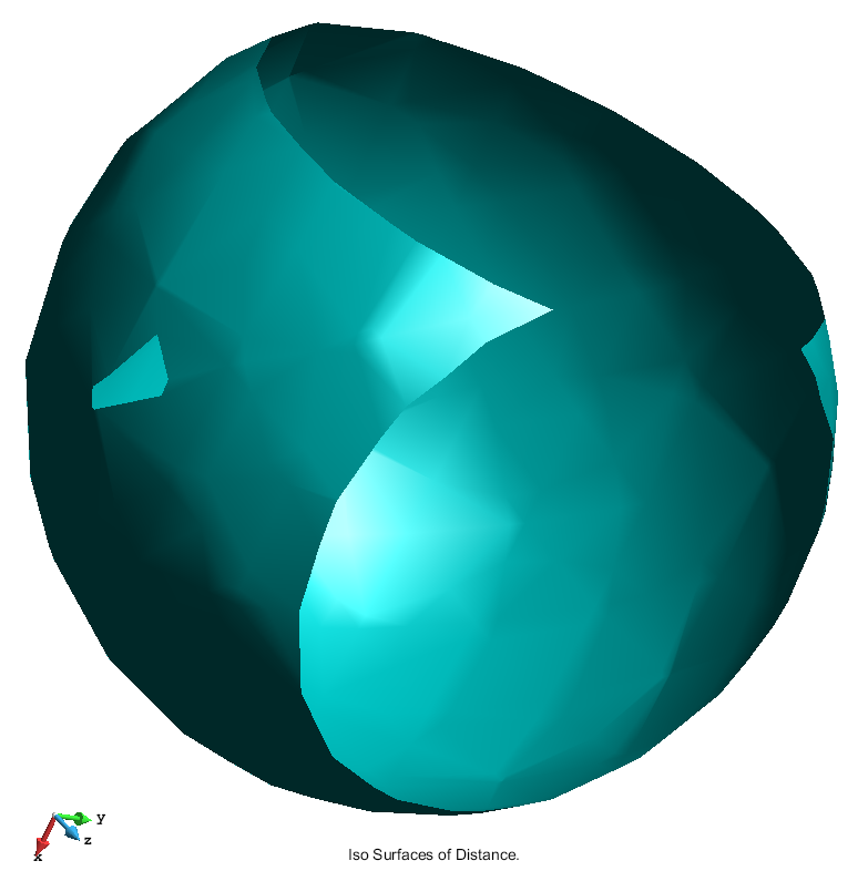
A field of signed distances to the embedded contours has been calculated on the nodes of the calculation volume mesh. They are stored with the model, and can be appreciated going to the post-processing part of GiD (where they are loaded as a result), and visualizing the contour fill of it, or some iso-surface (for instance).
|
|
| View of the contourfill of distances on the calculation volume mesh | View of the iso-surface of distance equal to 0 of the calculation volume mesh, where the sphere shape can be appreciated. |