GiD - The personal pre and post processor
Meshing basic features
- Enrique Escolano
- Abel Coll Sans
- Adrià Melendo
This course is focused in the basic meshing features and capabilities of GiD.
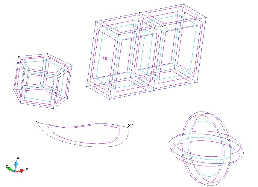
To follow this course, the models gid_model_basic_meshing_course.gid and gid_embedded_example.gid must be loaded from the folder where the courses material is.
 |
|
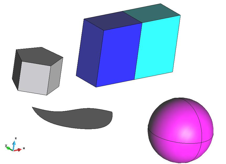
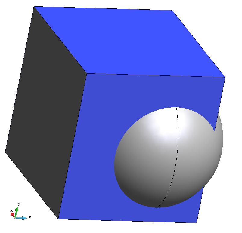
| View of the model used for most of the parts of this course | View of the model used for the embedded mesh part of the course |
In this course the three basic mesh types supported by GiD are shown:
- Body-fitted: this mesh type corresponds to a body-fitted Finite Elements-like mesh. The mesh is fitted to the contours of the geometrical entities.
- Embedded: This mesh type corresponds to an embedded mesh (not fitted to the contours of the embedded closed region). This kind of models have one or more geometrical volumes (the calculation volumes) and an embedded closed region. The calculation volumes are meshed in a body-fitted way, and its nodes have the extra information of (signed) distance to the contours of the embedded region.
- Cartesian: This mesh type corresponds to a Finite Differences-like mesh, a cartesian grid aligned to XYZ axes.
Default meshing settings
For this section we need to load the model gid_model_basic_meshing_course.gid
First of all we should reset all the meshing preferences in order to ensure the meshing options got from GiD are the same as the ones needed to reproduce exactly this course. For this purpose:
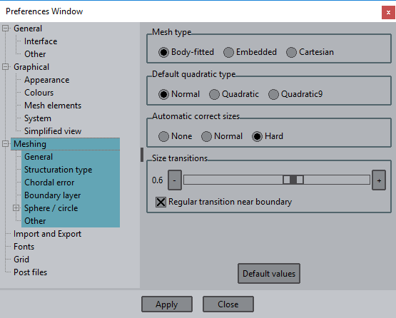
- Open the preferences window (Utilities->Preferences)
- Set the 'Meshing' branch.
- Shift+select last child of the branch: "Other".
- After selecting all meshing child's right click and select "Default values on selection".
- If some value has changed (it would be highlighted in red) you will need to Apply changes by clicking on "Apply" button.
If user does not assign any meshing property to the model, GiD generates body-fitted meshes and it assigns an automatic mesh size based on the size of the model. Elements by default are triangles (for surfaces) and tetrahedra (for volumes) and the mesh is unstructured. Let's have a look at this first automatic mesh.
- Select the option 'Generate mesh...' from the 'Mesh' menu.
- A window will appear asking for the mesh size to be used. For this model, the value proposed by GiD by default is 1. In this window the option 'Get meshing parameters from model' also appears. If this option is set, GiD loads the meshing parameters used the last time the model was meshed. Now unset this option, and click OK.
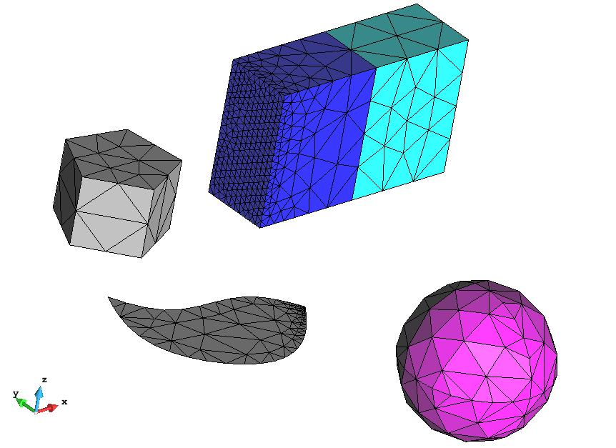
- A window will pop up giving the basic information of the result mesh (number of nodes and elements, memory consumed, etc.). Click on 'View mesh' and the following mesh should be shown:
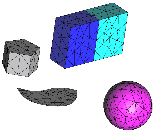
Mesh resulting using default options
Quadratic type
User can choose between different quadratic element types by selecting the 'Quadratic type' option in the 'Mesh' menu.
- 'Normal' option corresponds to the linear elements.
- 'Quadratic' option corresponds to the linear element with quadratic nodes in the middle of its edges.
- 'Quadratic9' option is like the Quadratic one, but with quadratic nodes also in the center of the faces of the element, and the center of the element. This quadratic type is only applied to quadrilateral, hexahedra or prism elements.
Let's make a quadratic mesh of the model.
- Select 'Quadratic' as the quadratic type in the mesh menu.
- Then generate the mesh again. The resultant mesh should look like the previous one, but if we zoom in at some area and we label all the nodes we should see that the elements are quadratic:
Detail of the mesh of a surface of the model, where all the nodes are labeled, so the quadratic nodes can be seen.
Types of body-fitted mesh
Different kinds of body-fitted meshes can be generated using GiD, depending on the topology required: unstructured, structured and semi-structured.
Set as 'Normal' the Quadratic type of the mesh (from Mesh menu) in order to reach the same meshes as the shown in this chapter.
Unstructured mesh
Assign sizes
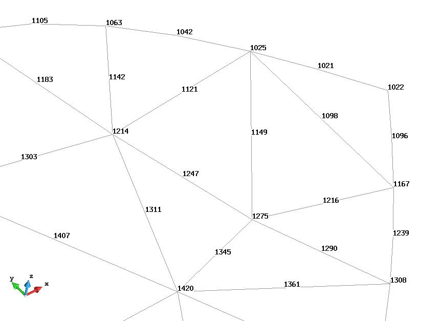
As said in previous steps, the default mesh generated by GiD is a unstructured mesh, and a general size is set to the whole model. However, it is possible to refine specific regions of the model by assigning different sizes to the geometrical entities. Let's see it in an example where the entities labeled in the following figure will have different size assigned.
Entities to be selected in the following steps to assign mesh size.
- Select the 'Unstructured->Assign sizes on surfaces' in the 'Mesh' menu, and set 0.2 in the appearing window.
- Click on Assign and assign the surface number 10. Then press ESCAPE to finish the selection, and close the size window.
- Select the 'Unstructured->Assign sizes on points' in the 'Mesh' menu and set 0.05 to the point number 22. Then press ESCAPE to finish the selection, and close the size window.
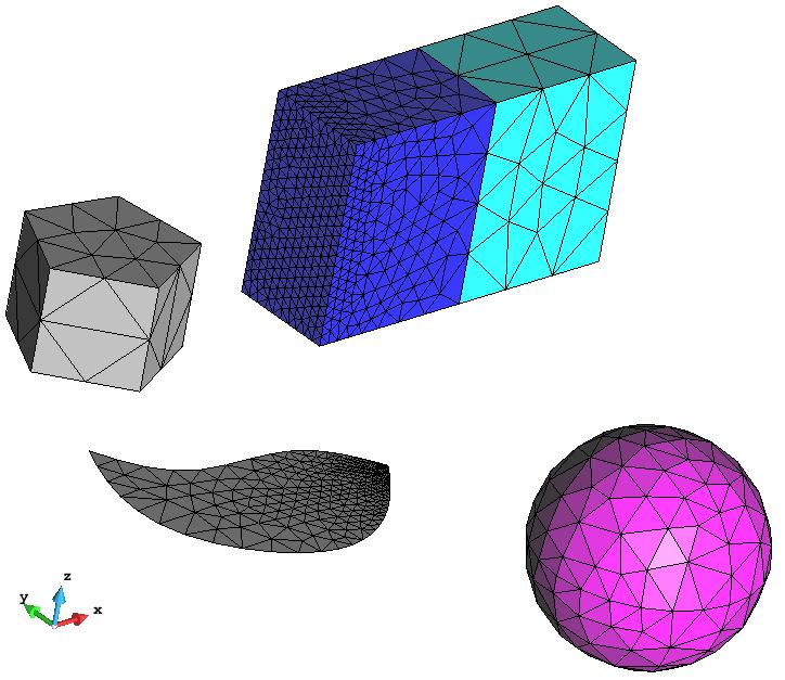
- Generate the mesh again (Mesh->Generate mesh), and the following mesh should appear.
Result mesh of the model once some specific sizes have been assigned.
Size transition factor
When different unstructured mesh sizes are present in the model, a transition between them is applied in the unstructured mesh. User can control whether this transition is smoother or sharper by the 'Unstructured size transitions factor'. This option is in the 'Meshing' branch of 'Preferences' window (Utilities->Preferences).
- Open the preferences window (in the 'Utilities' menu) and set the 'Unstructured size transitions factor' to 0.2 (this options is in the Meshing->General branch). Click 'Apply' and close the preferences window. Then generate the mesh again (Mesh->Generate mesh).
- Repeat the operation setting the 'Unstructured size transitions factor' to 0.9 to see the difference between the resultant meshes. Those meshes are shown in the next figure.
|
|
Surface meshers
There are three main unstructured surface meshers available in GiD: RFast ,RSurf and MinElem. While MinElem is a special mesher which tries to discretize the geometry using the less number of elements as possible considering a given chordal error criteria, RFast and RSurf try to generate the more regular elements as possible based on given mesh sizes.
This is a very simple geometrical model, but user may see the difference between the two main unstructured surface meshers RFast and RSurf. RFast mesher generates the mesh of the surface in the 2D parametric space of the surface, and RSurf generates it directly in the 3D space. This gives that meshers two basic properties:
- RFast mesher is faster, but in some cases it may give worse quality elements (more distorted).
- RSurf mesher is slower, but in general gives a better quality elements, in special in case of curved surfaces.
In this model the only curved surfaces are the ones of the sphere, and it is hard to see the difference of quality between both meshers. However we can see a slight difference between them.
- Open the 'Preferences' window (from the 'Utilities' menu) and set the RFast mesher in the Meshing branch. Set the 'Unstructured size transitions' factor to 0.6.
- Apply changes and generate the mesh.
- Repeat this process setting RSurf as surface unstructured mesher.
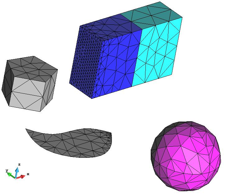
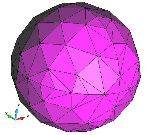
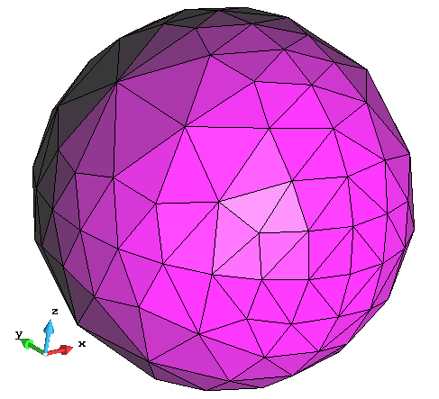
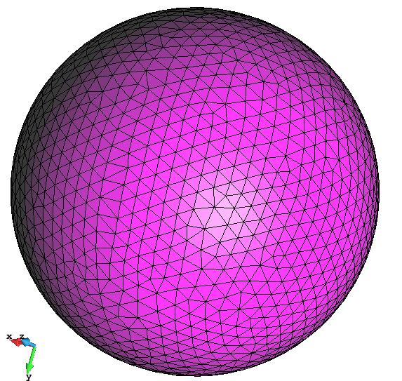
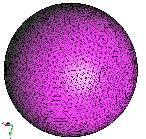
In the following figure the results meshes of the sphere are shown using RFast an RSurf meshers:
Mesh of the sphere of the model using RFast mesher. |
Mesh of the sphere of the model using RSurf mesher. |
In complex geometrical models in which the surfaces curvatures are important it is strongly recommended to use RSurf mesher in order to get a high-quality final mesh.
If the MinElem mesher is selected, it can be seen that the surfaces meshes of the model are quite different. Specially in planar shapes, where few elements are used to generate the mesh, but in some cases they are highly distorted. To appreciate better the difference between the meshes generated by MinElem mesher, reset the meshing sizes already assigned (Mesh→Reset mesh data) and generate a mesh with a very large mesh size (for instance, 1000).
Mesh of the model using MinElem as surface mesher.
This kind of meshes are mostly used for visualization purposes, or for simulations where the quality of the elements is not crucial, improving the performance of the computations due to the reduced number of elements.
It has to be considered that the surface mesher can also be assigned to specific surfaces, so as not all the model is meshed with the same one. This can be done in the 'Mesh' menu, by the 'Unstructured→surface mesher' option.
Volume meshers
GiD has three unstructured volume meshers (all of them generating tetrahedra): Advancing front, Tetgen and Octree.
The main characteristics of them are the following ones:
- Advancing front: it is based on advancing front technique. It may be slow, but it typically generates better quality elements.
- Tetgen: it is based on Delaunay method, and it is faster than the previous one. In some cases it may lead to poor quality elements near the boundaries of the volumes.
- Octree: it is an octree-based mesher, which is very fast and robust. This mesher can skip lines which are part of the contours of the volume, if they have no specific property assigned.
First of all, reset the meshing data (Mesh->Reset mesh data).
We will focus on the sphere volume (volume number 3). For this purpose we will not mesh the rest of the entities. So, set 'Mesh->Mesh criteria->No mesh' and select the other volumes of the model, as well as the isolated surface (surface number 18).
In order to appreciate better the difference between the difference volumes meshers, let's unset the 'Automatic correct sizes' in the Mesh branch of the Preferences window (set it to None). Set also as unstructured surface mesher the RSurf one.
Generate the mesh of the model with a size of 0.2 setting the three types of unstructured volume mesher (one mesh for each mesher). The results of the mesh are shown in the following figure:
|
|
One can appreciate that the different meshers generate different number of elements, and they are not equally fast.
The external view of the ones generated by Advancing front and Tetgen is the same, as they are constrained meshers and they use the same surface mesh as an input. This is not the case of the Octree mesh, where the regular grid of the octree structure can be appreciated in the nodes distribution (specially if we take a look at the mesh in 'render normal' mode, and we rotate it).
It can also be seen that the lines of the volume surfaces are not represented in the mesh coming from the octree mesher.
Structured mesh
Structured meshes can also be generated in GiD. Structured meshes are the ones got from a predefined pattern, and they are restrictive in the topology of the geometrical entities they are applied in.
- Structured surfaces must be '4-sided' surfaces; this means that they must have four lines, or four clear angles close to 90 degrees, so as the mesher could make a topological correspondence between the contour of the surface and a square.
- Structured volumes must have 6 contour surfaces (the mesher will make a topological correspondence between the volume and a cube).
Actually, GiD can also generate center-structured surface meshes (which have other topological requirements), but they are not included in this chapter.
Let's see an example of how to assign this meshing property, but first of all it is better to un-assign the previously assigned meshing properties to focus just in this structured part.
- In order to un-assign the mesh properties assigned to the model click on the 'Reset mesh data' option in the 'Mesh' menu.
Lets assign structured meshing type to the volume number 5 and surface number 10 (shown in the following figure).
Entities to be set as structured.
In order to set a structured mesh onto a geometrical entity, the number of divisions (or the size) in its contour lines must be set.
- Select 'Mesh->Structured->Surfaces->Assign number of divisions to surface lines' and select the surface number 10. Then press ESCAPE to leave the selection mode.
- Set the number of divisions to 3 and select all its contour lines.
- Select 'Mesh->Structured->Volumes->Assign size to volume lines' and select the volume number 5. Then press ESCAPE to leave the selection mode.
- Set a size of 0.5 and select the contour lines of the volume.
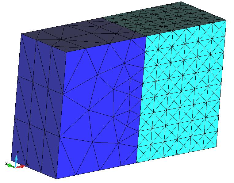
- Now generate the mesh again, and the result mesh should be like the one shown in the following figure:
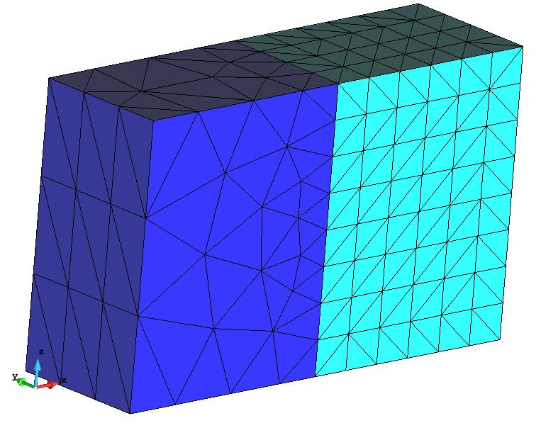
View of the structured mesh of some entities of the model
The structured pattern of elements is clearly recognized in the entities we have selected.
Different number of divisions can be set to the different structured directions of the entities. You can try to set different numbers and see how the final mesh changes.
In case of triangles and tetrahedra, the structured mesh comes from an internal splitting of an intermediate mesh made of quadrilateral or hexahedra. The way these elements are splitted can be symmetrical or not, depending on the 'Symmetrical structured' variable of the 'Meshing→Structuration type' branch of Preferences window.
Setting the tetrahedra to be symmetric, for example, would give a mesh like the shown in hereafter:
View of the structured mesh of some entities of the model, setting as 'Symmetric structured' the tetrahedra.
Semi-structured mesh
Semi-structured meshes can be applied to volumes. This kind of meshes follows a prismatic topology, so these volumes must be prismatic: two tops can be identified, as well as a number of lateral surfaces (which must be able to be meshed as structured).
In the model of this course, the volumes number 1, 4 and 5 are prismatic, so they can be meshed with semi-structured volume.
- Again, reset the mesh data previously assigned (Mesh->Reset mesh data).
Let's make semi-structured the volumes 1 and 4.
- Select Mesh->Semi-structured->Volumes->Assign number of divisions to volume lines
and set as 4 the number of divisions to be assigned.
- Then select volumes number 1 and 4 and press ESCAPE to leave the selection mode.
- Generate the mesh. The result should be as the one shown in the following figure:
Detail of the semi-structured mesh of the volumes 1 and 4.
Change structured direction
Volume number 1 is topologically prismatic only in one direction, but volume number 4 is prismatic in its 3 directions (as is has 6 boundary surfaces). The structured direction of volume 4 has been set automatically by GiD, but user may want to set another one.
- Select Mesh->Semi-structured->Volumes->Set structured direction. Then select line 25 (the line labeled in the next figure).
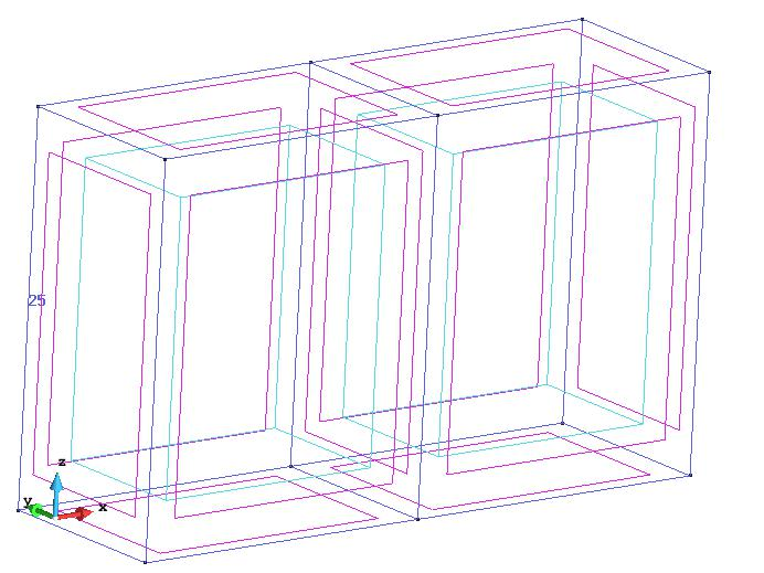
Line 25, to be set as structured direction.
Generate the mesh again. The resulting mesh should be as this one:
Semi-structured mesh when structured direction of volume 4 is the one defined by line 25.
GiD offers two options to force the structured direction of a semi-structured volume: set the structured direction via a line following that direction (the option just done before), or set one of the tops of the prism ('Mesh->Semi-structured->Set->Master surface').
Element types
The different element types GiD can generate are the following ones:
- Surface: triangle, quadrilateral, circle
- Volume: tetrahedra, hexahedra, prism, spheres and points.
There are some limitations in terms of element types permitted depending on the mesh type:
- hexahedra and prism elements can only be generated in structured or semi-structured volumes.
- Embedded meshes are only implemented for tetrahedra volume elements
- Cartesian meshes only generate hexahedra (for volumes), quadrilateral (for surfaces) and line (for lines) elements.
Considering this, selecting an element type is as easy as going to the 'Mesh' menu, setting the 'Element type' and select the desired entities.
In order to see different types of elements on this model follow this steps:
- Reset previous mesh data (Mesh->Reset mesh data).
- Set as structured volume number 4, with 5 divisions in its contour lines.
- Set as semi-structured volume number 5 with 5 structured divisions.
- Set Hexahedra as element type for volume number 4.
- Set 'Sphere' as element type of the spherical volume (volume number 3).
- Set 'Quadrilateral' as element type of surface number 18.
To check graphically the element types (or other meshing properties) assigned to the model, the 'Draw' option in the 'Mesh' menu is useful.
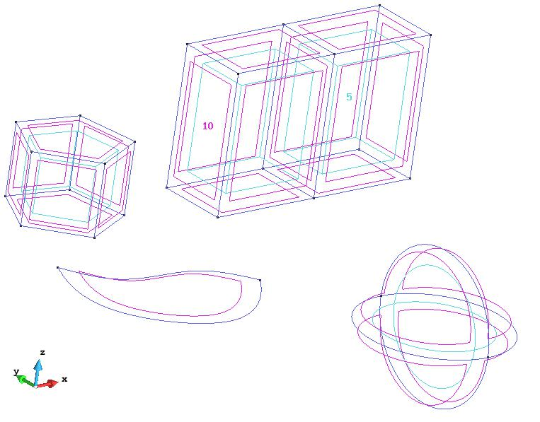
- Select Draw->Element type->Volumes in order to check the element types assigned. The result should be like the following image:
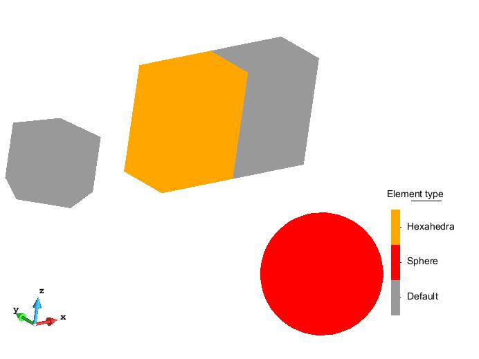
Different element types assigned to the model volumes shown using the Mesh->Draw option.
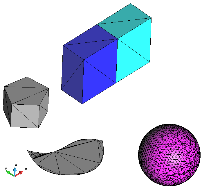
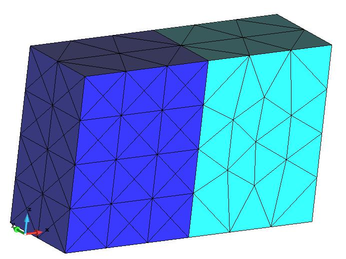
- Generate the mesh. The resulting mesh should be like the one shown in the following figure:
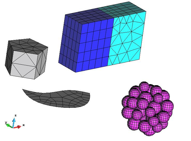
View of the mesh generated with the different element types assigned.
Note that the element type of volume 5 is prism, but the user has not set it. Just before mesh generation, GiD makes compatible the element types of the geometrical entities in order to fit the user requirements.
Cartesian mesh
To generate a Cartesian mesh of the model, set this mesh type in the Meshing→General branch of the preferences window. Once this option is selected, the 'Cartesian' branch appears in the Meshing part of the Preferences window.
We will leave all the default values and generate the mesh with a size of 0.5.
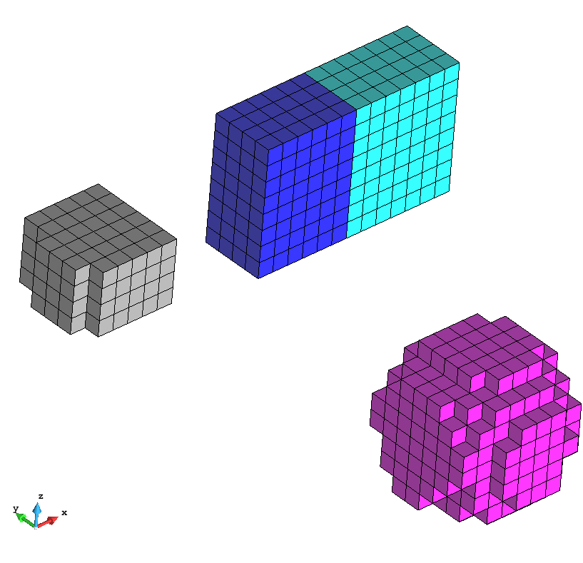
View of the cartesian mesh of the model generated with size 0.5.
It can be seen (in the Meshing→Cartesian branch of preferences window) that the default Cartesian mesher of GiD (Scan convert) is only generating volume elements. To generate line or surface elements, the mesher 'Zmesher' can be used.
Embedded mesh
For this section, we will work with the model gid_embedded_example.gid (it can be loaded from the folder where the courses material is). This model have a cubic volume, and the skin surface of a sphere.
As explained before, an embedded model consists in some volumes (the calculation volumes), and embedded regions defined by collection of surfaces. In this case, the calculation volume is the cube, and the embedded region is defined with the sphere surfaces.
First of all, select the 'Embedded' mesh type in the Meshing→general branch of the preferences window.
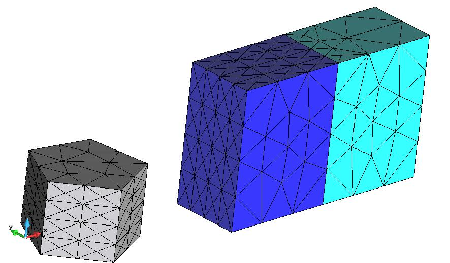
Then, generate the mesh of the model (Mesh→generate), using a general mesh size of 1. The following mesh should be generated:
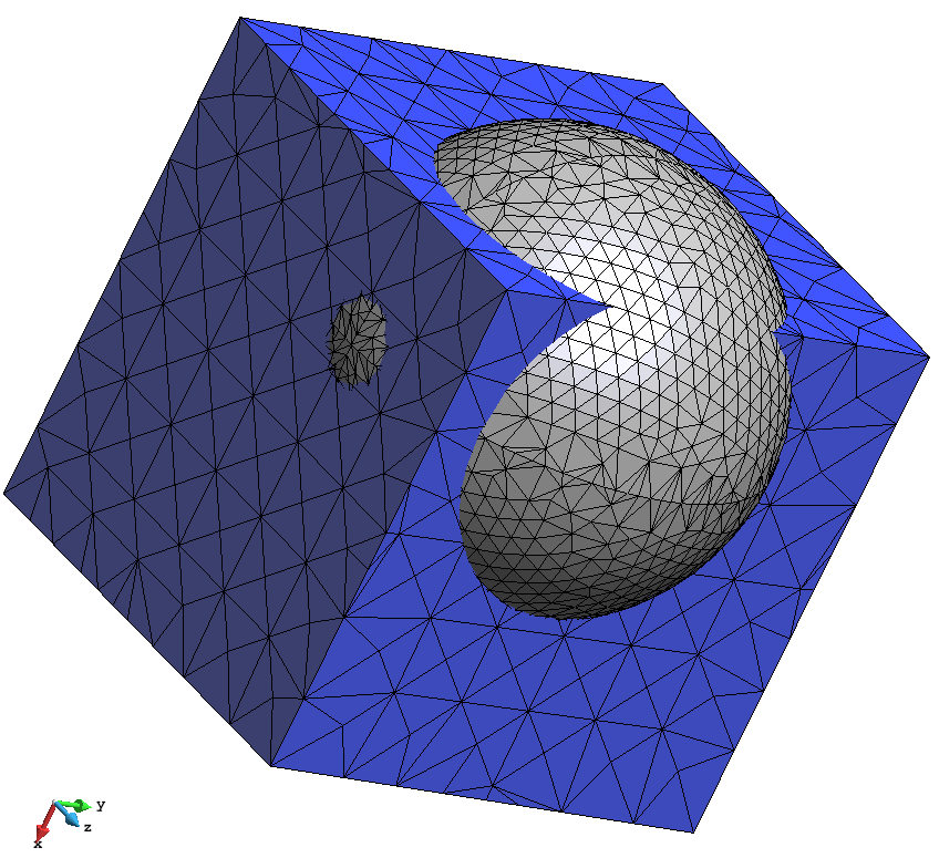
View of the mesh generated.
As an embedded mesh, it can be seen that the volume mesh is fitted to the calculation volume (cube), and it is not conformal nor body-fitted to the embedded region (sphere skin).
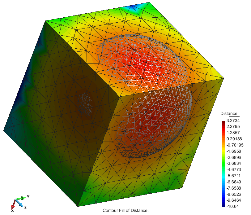
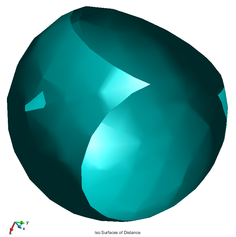
A field of signed distances to the embedded contours has been calculated on the nodes of the calculation volume mesh. They are stored with the model, and can be appreciated going to the post-processing part of GiD (where they are loaded as a result), and visualizing the contour fill of it, or some iso-surface (for instance).
|
|
| View of the contourfill of distances on the calculation volume mesh | View of the iso-surface of distance equal to 0 of the calculation volume mesh, where the sphere shape can be appreciated. |
COPYRIGHT © 2022 · GID · CIMNE