GiD - The personal pre and post processor
Mesh format: ModelName.post.msh
Note: This postprocess mesh format requires GiD version 6.0 or higher.
Comments are allowed and should begin with a '#'. Blank lines are also allowed.
To enter the mesh names and result names in another encoding, just write # encoding your_encoding
for example:
# encoding utf-8
Inside this file one or more MESHes can be defined, each of them should:
- Begin with a header that follows this model:
MESH "mesh_name" dimension mesh_dimension Elemtype element_type Nnode element_num_nodes
where
- MESH, dimension, elemtype, nnode: are keywords that are not case-sensitive;
- "mesh_name": is an optional name for the mesh;
- mesh_dimension: is 2 or 3 according to the geometric dimension of the mesh;
- element_type: describes the element type of this MESH. It should be one of the following; Point, Line, Triangle, Quadrilateral, Tetrahedra, Hexahedra, Prism, Pyramid, Sphere, Circle ;
- element_num_nodes: the number of nodes of the element:
- Point: 1 node,
Point connectivity:![]()
- Line: 2 or 3 nodes,
Line connectivities:![]()
![]()
- Triangle: 3 or 6 nodes,
Triangle connectivities:
- Quadrilateral: 4, 8 or 9 nodes,
Quadrilateral connectivities:


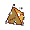
- Tetrahedra, 4 or 10 nodes,
Tetrahedra, connectivities: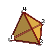
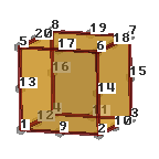
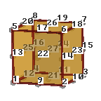
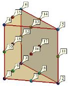
- Hexahedra, 8, 20 or 27 nodes.
Hexahedra, connectivities: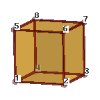
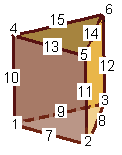
- Prism: 6, 15 or 18 nodes,
Prism connectivities: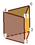
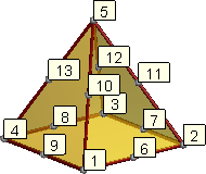
- Pyramid: 5 or 13 nodes,
Pyramid connectivities: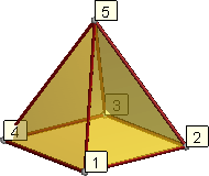
- Sphere: 1 node and a radius
- Circle: 1 node, a radius and a normal (x, y, z)
Note: For elements of order greater than linear, the connectivities must written in hierarchical order, i.e. the vertex nodes first, then the middle ones.
- An optional line declaring the units of the mesh coordinates
Unit "mesh unit"
- An optional line describing its colour with # color R G B A, where R, G, B and A are the Red, Green, Blue and Alpha components of the color written in integer format between 0 and 255, or in floating (real) format between 0.0 and 1.0. (Note that if 1 is found in the line it will be understood as integer, and so 1 above 255, rather than floating, and so 1 above 1.0). Alpha values represent the transparency of the mesh when this visualization options is active, being 0.0 totally opaque and 1.0 totally transparent.
# color* 127 127 0
In this way different colours can be specified for several meshes, taking into account that the # color line must be between the MESH line and the Coordinates line.
- Be followed by the coordinates:
coordinates
1 0.0 1.0
3.0 . . .1000
-2.5 9.3 21.8
end coordinates
where
- the pair of keywords coordinates and end coordinates are not case-sensitive;
- between these keywords there should be the nodal coordinates of all the MESHes or the current one.
Note: If each MESH specifies its own coordinates, the node number should be unique, for instance, if MESH "mesh one" uses nodes 1..100, and MESH "other mesh" uses 50 nodes, they should be numbered from 101 up.
- Be followed by the elements connectivity
elements
#el_num node_1 node_2 node_3 optional_material_number
1 1 2 3 215
. . .
1000 32 48 23 215
end elements
where
- the pair of keywords elements and end elements are not case-sensitive;
- between these keywords there should be the nodal connectivities for the my_type elements.
Note: On elements of order greater than linear, the connectivities must written in hierarchical order, i.e. the vertex nodes first, then the middle ones;
- There is optionally a material number.
- For Sphere elements : Element_number Node_number Radius [optional_material_number]
- For Circle elements : Element_number Node_number Radius [optional_normal_x optional_normal_y optional_normal_z] [optional_material_number]
If the normal is not written for circles, normal ( 0.0, 0.0, 1.0) will be used.
COPYRIGHT © 2022 · GID · CIMNE