GiD - The personal pre and post processor
Generating the cartesian mesh
- Enrique Escolano
- laura santos
- Miguel Pasenau
We are going to use the previous model named "ToMesh3.gid", open this model.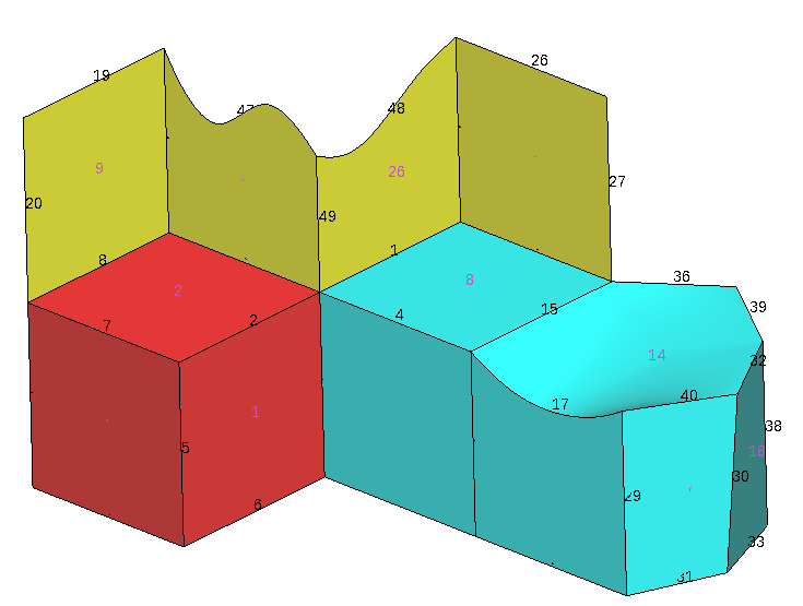
Set in preferences
mesh type: Cartesian,
then in the cartesian branch set
mesher: Scan convert
The Shape to be meshed could be set to: From mesh or from geometry.
In case of 'From mesh' an auxiliary unstructured mesh of triangles will be generated and will be used as input for the cartesian mesher. This intermediate mesh will be deleted at the end, and in any moment will be visible for the user.
In case of 'From geometry' then the triangles of the 'render mesh' of the geometry will be used. This option could be faster if the render mesh was previously created. A drawback is that in GiD the render mesh may not be conformal between entities, and has small gaps, but usually do not affect the cartesian mesher.
Usually both shapes will generate similar cartesian meshes.
Left initially all default values and generate a mesh (menu: Mesh->Generate mesh) with general size=2 units
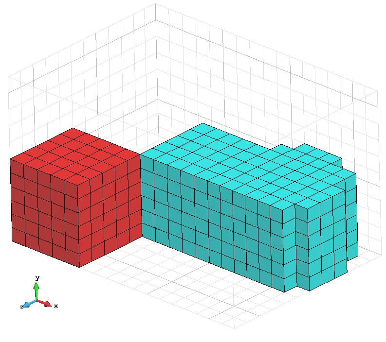
Then automatically is calculated a grid fitted (approximately) to the bounding box of the shape, with a cell size of 2 units in all directions X Y Z, and a cartesian mesh of hexahedra is generated. Note that the green surfaces were not meshed.
Note: This mesher could only generate 3D meshes for volumes (hexahedra), or 2D meshes for surfaces, all in z=0. It cannot generate in 3D meshes of faces for surfaces or edges for curves.
The 'lower-right' grid icon ![]() switch on/off the drawing of the underlying grid
switch on/off the drawing of the underlying grid
In this case, the default Spacing was set to Variable, but the result looks very similar to a Uniform mesh (all cells seems equal-spaced in all directions)
Now assign to the volume number 3 a specific size=0.8 in all directions. Select
Mesh->Assign cartesian size→Volumes

and select the volume number 3 (on the right of the images) finishing with a double <Esc>
and generate again a mesh with general size=2.0. You will obtain a non-uniform mesh like these:
In case of Variable spacing, the Minimum size try to avoid a too small edge size, and the Size ratio try to avoid big differences of sizes between two consecutive edges.
The grid is automatically defined when generating the mesh (based on the current geometry and mesh sizes), but the user could set its own definition:
In preferences check User defined, press Apply to accept it, and then the Grid window... button become enable. Pressing it, a window like the following one appears, filled with the current values:

In this window it is allowed to modify the location and size of the box, set the number of divisions and set the values of the ticks editing the values of the table.
The 'Auto calculate' button allows to fill automatically all fields, based on the geometry and mesh sizes (similar to the case of generating a mesh with this size)
Changing only the (lower left) corner, the box size or the amount of divisions and pressing 'Apply' will try to set the data of the row, maintaining the other data.
E.g. if we modify the Num grid Z (third value) from 24 to 10 ticks and press the Apply button of its row then the Z grid values of the table change (to have an increasing array of 10 values normalized from 0.0 to 1.0)
Then if we generate again a mesh with general size=2.0 we obtain this mesh: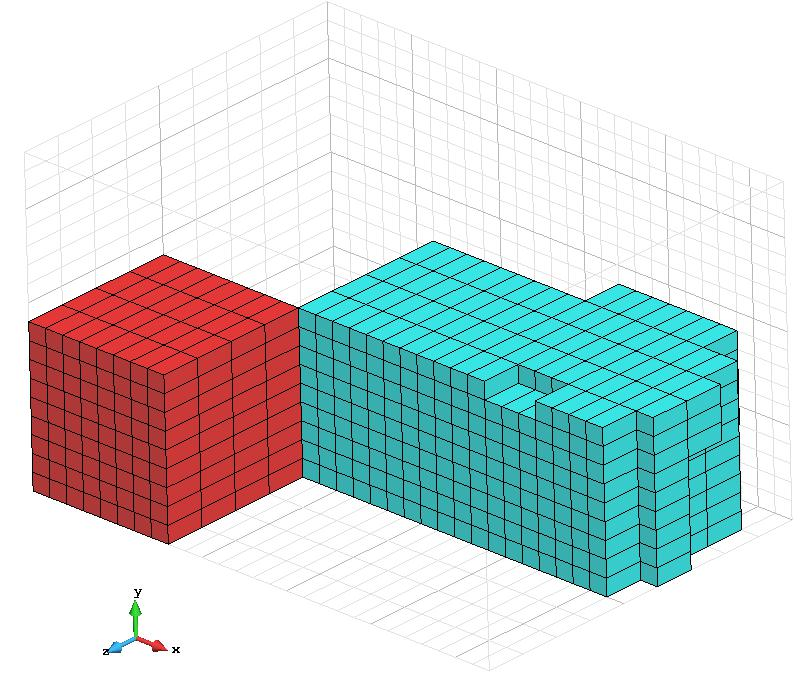
Related content
COPYRIGHT © 2022 · GID · CIMNE