GiD - The personal pre and post processor
Description of the local axes
Local axes definition
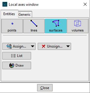
CustomLib lets the user to define new coordinates reference systems. Local axes can be assigned to entities using the Local axes window.
Local coordinates systems of lines are defined such that the local x-axis will correspond to the axial direction of the line. Both other axes will be defined perpendicular to this local x-axis.
Local coordinate systems of surfaces are defined such that the local z-axis is defined perpendicular to the surface and both x- and y- axes are defined perpendicular to each other in the plane of the surface.
Local coordinates can be defined by selecting the option called Assign Automatic in the Local axes window. Selecting the option Assign Automatic alt will define alternative local coordinate systems which are normally rotated 90 degrees around the third axis compared to the first ones.
The procedure gid_groups_conds::local_axes_window creates the Local axes window automatically, which allows to define the local axes to be used.
Local coordinates will be shown by selecting the Draw button.
It should be emphasized that it is possible to list the local axes clicking on the 'List' button. This way a child window displays both the Euler angles and the transformation matrix.
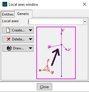
Generic local axes window allows to create new local axes in two ways:
- Three points XZ: Enter three points that corresponds to the origin, the X-direction and the Z-direction. The origin and the last introduced point define the Z-axis, whereas the second point indicates the side of the x-z plane where the point lies.
- X and angle: Enter two points and one angle. The first point is the center, the second point indicates the x-axis and the angle indicates the position of the Y and Z axes. In the graphical window it is possible to set this angle by moving the mouse on the screen. It also indicates where the origin of the angle is. The angle can be entered either by clicking the mouse or by entering the exact value in degrees.
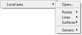
User defined local axes menu
CustomLib also offers the opportunity to customize the pull-down menu when creating a problem type in the following way:
User can create different named local axes systems and with the different methods that can be chosen there. The names of the defined local axes will be added to the menu, where local axes are chosen.
The code to make this change in the menu would be as follows,
GidAddUserDataOptionsMenu [= "Local axes"] "gid_groups_conds::local_axes_menu %W" $ipos
The 'ipos' is the index where the new menu will be inserted.
For more details about managing menus reference is made to the 'Managing menus' chapter in the Gid manual.
It is important to note that all user-defined systems are automatically calculated in the problem type. After generation of the mesh, the local coordinates of entities will be automatically defined at each entity element of the entities local coordinates have been defined on.
Local axes assigned on lines
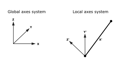
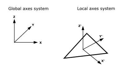
The model has been created related to a global axis system XYZ that is unique for the entire problem. The main property of this system is that the local X’ axe must have the same direction than the line.
The ways for defining local axes systems are:
-Default. The program assigns a different local axes system to every line with the following criteria:
X’ axe has the direction of the line. If X’ axe has the same direction than global Z axe, Y’ axe has the same direction than global X. If not, Y’ axe is calculated so as to be horizontal (orthogonal to X’ and Z). Z’ axe is the cross product of X’ axe and Y’ axe. It will try to point to the same sense than global Z (dot product of Z and Z’ axes will be positive or zero). The intuitive idea is that vertical lines have the Y’ axe in the direction of global X. All the other lines have the Y’ axe horizontal and with the Z’ axe pointing up.
-Automatic: Similar to the previous one but the local axes system is assigned automatically to the line by GiD. The final orientation can be checked with the Draw Local Axes option in the GiD Conditions window.
-Automatic alt: Similar to the previous one but an alternative proposal of local axes is given. Typically, user should assign Automatic local axes and check them, after assigning, with the Draw local axes option. If a different local axes system is desired, normally rotated 90 degrees from the first one, then it is only necessary to assign again the same condition to the entities with the Automatic alt option selected.
Local axes assigned on surfaces
The model is created related to a global axis system XYZ that is unique for the entire problem. The main property of this local axis system is that the local Z’ axe must have the same direction than the normal of the element.
The ways for defining local axes systems are:
-Default: The program assigns a different local axes system to the surface with the following criteria:
Be N the unitary normal of the surface element, and U the vector (0,1,0) and V the vector (0,0,1). Then:
Z’ axe has the direction and sense of N.
If Nx<1/64 and Ny<1/64, then X’ axe will be in the direction of the cross product of U and N (UxN).
- If not, X’ axe will be in the direction of the cross product of V and N (VxN).
- Y’ axe will be the cross product of Z’ axe and X’ axe.
Intuitively, this local axis system is calculated so as if element is approximately contained in the plane XY, local X’ axe will point towards global X axe. If not, this X’ axe is obtained as orthogonal to global Z axe and local Z’ axe.
-Automatic: Similar to the previous one but the local axes system is assigned automatically to the surface. The final orientation can be checked with the Draw Local Axes option in the GiD Conditions window.
-Automatic alt: Similar to the previous one but an alternative proposal of local axes is given. Typically, user should assign Automatic local axes and check them, after assigning, with the Draw local axes option. If a different local axes system is desired, normally rotated 90 degrees from the first one, then it is only necessary to assign again the same condition to the entities with the Automatic alt option selected.
Example no. 1
This is an example of the <container/> node field in the .spd file to call the Local axes window from the data tree:
<container n="local_axes" pn="Local axes">
    <container n="local_axes_window" pn="Local axes definition">
        <edit_command n="local_axes_win" proc="gid_groups_conds::local_axes_window" edit_type="exclusive"/>
    </container>
</container>
Example no. 2
Here is an example of application for opening the Local axes window from a conditions window, as follows:
The <condition> node field in the .spd file is:
<condition n="local_axes" pn="Local axes condition" ov="surface" local_axes="normal" ovm="element"/>
The local_axes attribute specifies one of the three states for the button: normal, disabled or hidden.
Example no. 3
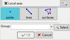
This is an example of Local axes check button definition inside a window of the data tree. If the check button is activated, then the Local axes window can be opened pressing the button at the right:
The <condition> node field in the .spd file is the following:
<condition n="pressure_load" pn="Pressure load" ov="surface" ovm="element">
<value n="load_type" pn="Load type" v="global" values="global,local" local_axes="disabled" editable="0" help="The load can be applied in global axes, or in the Local Axes defined for the entity">
       <dependencies node="." att1="local_axes" v1="normal" value="local"/>
       <dependencies node="." att1="local_axes" v1="disabled" not_value="local"/>
</value>
</condition>
Example no. 4
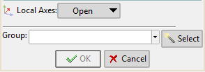
Here is an example of Local axes definition, inside for instance, a conditions window of the data tree.
The non-editable combobox In the combobox options The <condition/> node field in the .spd file could be the following:
<condition n="pressure_load" pn="Pressure load" ov="surface" ovm="element">
<value n="load_type" pn="Load type" v="global" values="global,local" local_axes="disabled" editable="0" help="The load can be applied in global axes, or in the Local Axes defined for the entity">
       <dependencies node="." att1="local_axes" v1="normal" value="local"/>
       <dependencies node="." att1="local_axes" v1="disabled" not_value="local"/>
</value>
</condition>
Example no. 5
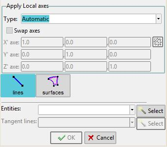
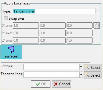
The following is an example for creating a specific window for assigning local axes on surfaces in the data tree. The user selects a group of lines and axe X' will be tangent to the lines:
The item 'Local axes definition' in the data tree opens the following window:
The <condition> node field in the .spd file is as follows:
<condition n="local_axes_directions" pn="Local axes directions" ov1="surface" ov2="line" ov1p="Local axes surfaces" ov2p="Tangent lines" ovm1="element" ovm2="none" help="Select surfaces in order to define its local axes tangents based in selected lines" />
Future developments
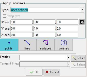
In the future it will be available a new Local axes window, totally integrated in the data tree, that will allow to define groups composed by local axes.
There will be different styles of local axes definitions:
- Automatic: The program automatically generates one local axes compatible with the geometry.
Note: If swap axes check button is selected, axes X' and Y' are swapped.
- Tangent lines: User selects a group of lines and axe X' will be tangent to these lines:
- User defined: User defines the three local axes X', Y' and Z':
COPYRIGHT © 2022 · GID · CIMNE
