GiD - The personal pre and post processor
Meshing advanced features
This course is focused in exploring the advanced meshing features present in GiD. It is recommended to follow the basic meshing course before this one.
Skip entities
Using classical surface meshers, all the lines of the model are meshed, so the user is not allowed to generate elements larger than the surface they belong to.
Using GiD, it is possible to skip the inner lines between surfaces in contact. This option is very interesting in the cases were the geometrical definition of the model use high distorted surfaces, or very small ones in comparison with the elements size required for the simulation.
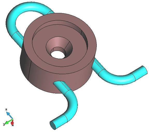
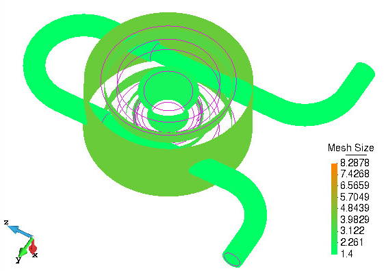
In this course we will use the model model_skipentities.gid, which is a geometrical model of a mechanical part depicted in the following picture:
View of the model of a mechanical part used in this course.
Mesh using automatic parameters
First of all we are going to generate a mesh with all the default parameters in GiD.
- Select the Reset mesh data option from the Mesh menu.
- Open the Preferences window and set the Default values in the meshing branch. To set the Default values in all the branches of Meshing, you should click the right mouse button, and set the Default values on selection option. Then click on Apply and close the window.
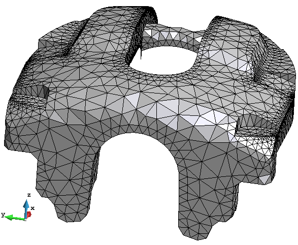
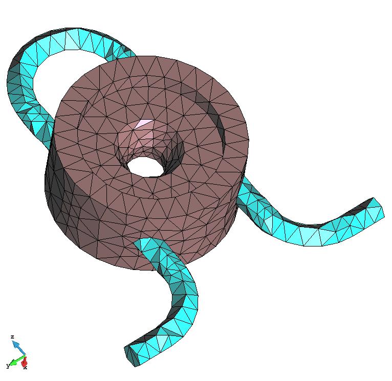
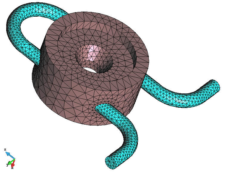
- Generate the mesh (for instance using the shortcut Control-g) setting to 9 the general mesh size. The generated mesh should look like this:
View of the mesh generated with the default meshing parameters of GiD.
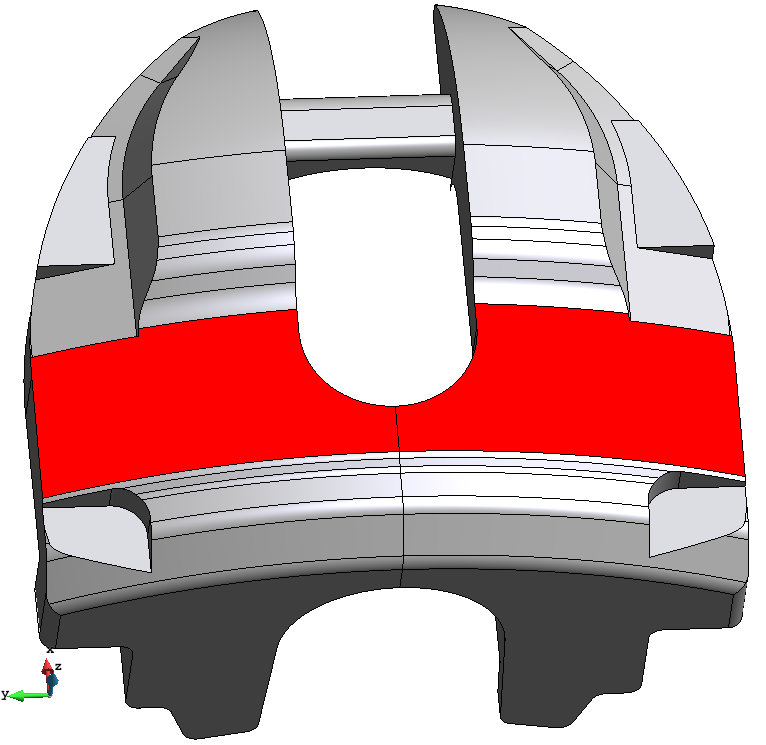
It can be seen that the regions where the original surfaces are very thin make the mesher generate elements fitted inside those surfaces' contour lines. In the following figure some of these surfaces and its related elements are highlighted in red:
|
|
| Some thin surfaces highlighted in red. | The elements corresponding to the thin surfaces highlighted. |
Skip entities automatically
If a mesh with a more uniform element size distribution is required, the Skip entities automatically (Meshing branch in the Preferences window) option should be set. With this option, following entities will be skipped when meshing:
- points belonging to two lines which are tangent enough at that point.
- lines belonging to two surfaces which are tangent enough at that line.
The tangent enough concept is defined by a maximum angle formed by the lines (in case of points) or the normals of the surface (in case of lines). The default angle is 10 degrees, and can be set as well from the preferences window.
Other criteria are applied in order to allow or not an entity to be skipped:
- Entities with some material, condition or group assigned are never skipped.
- Entities which parents have different groups, materials, or conditions applied are never skipped.
Let's see how it works.
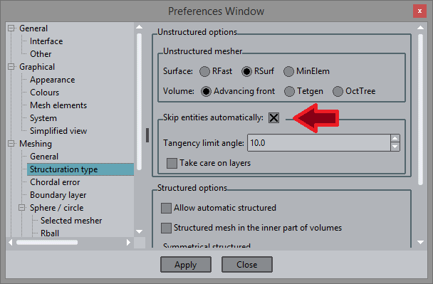
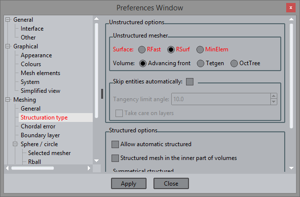
- Open the Preferences window, and set the Skip entities automatically group option in the Meshing --> Structuration type branch from the Preferences window:
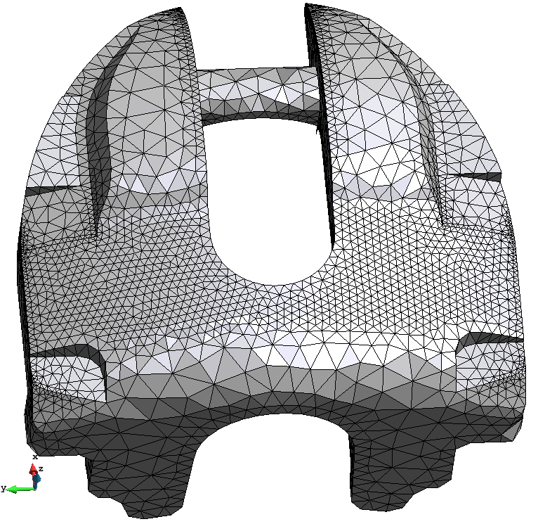
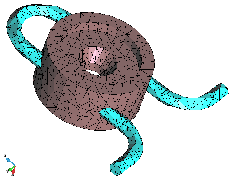
- Generate the mesh with the same size as before (size equal to 9). The resulting mesh should look like the following one:
Mesh of the model using the 'Skip entities automatically' option.
As can be seen, now the elements are larger than in the mesh generated with the default options. In this case, the mesher is not forced to mesh all the lines and points of the model, so the triangles can be larger than the surfaces they belong to.
Note that the lines which form a sharp edge between the surfaces they belong to are not skipped.
It has to be pointed out that the nodes of the mesh are exactly placed onto the surfaces.
Often when meshing with the skip the entities automatically option enabled is more difficult than using the conventional approach. In some complex geometrical models, sometimes the mesher cannot skip the desired entities, so GiD may generate the meshes without skipping any entity.
Skip entities automatically: Assign sizes
Although this option allows to generate mesh patches of surfaces together, user can assign different element sizes to the different surfaces or lines, and these sizes will be considered during the mesh process. Let's see it in an example:
- Assign 3 as unstructured size of the surfaces highlighted in the following figure (select Mesh --> Unstructured --> Assign sizes on surfaces from the top menu bar, enter 3 in the window that appears and select these two surfaces, and close the window):
Surfaces which unstructured size must be 3.
- Generate again the mesh with 9 as the general size. The resulting mesh should look like the following one:
View of the mesh skipping entities automatically and assigning a size of 3 in some surfaces
As it can be seen, the size of the elements in the region of the selected surfaces has been modified, although the lines between 'tangent enough' surfaces are still skipped.
Skip specific entities
As it has been seen in the previous points, skipping entities automatically all the lines and points accomplishing the given tangency criteria are skipped. However, the user may want not to skip some entities, or skip just a specific line or point (not all of them). For this purpose the user may use the Skip options in the Mesh criteria part of the Mesh menu.
Accordingly to the easier way of setting the parameters for meshing, user may be interested in one of these two options:
- Skip almost all the entities accomplishing the automatic skip criteria except some line or point. In this case, Skip entities automatically option must be set in the Preferences window, and user may select manually the entities not to be skipped ( Mesh --> Mesh criteria --> No Skip --> Points / Lines).
- Only skip some specific entity (and don't skip the major part of entities of the model). In this case, Skip entities automatically must be unset from the Preferences window, and the entities to be skipped must be selected manually ( Mesh --> Mesh criteria --> Skip --> Points / Lines).
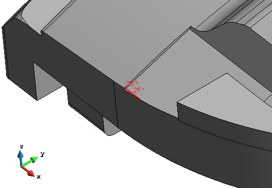
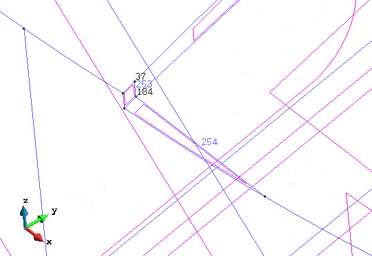
Let's see an example of the second case. Imagine we only want to skip lines number 253 and 254 and points number 37 and 184. In the following figure the region were these entities are is highlighted in red, as well a zoom of the zone is presented with the corresponding labels in this area.
|
|
| Entities to be skipped highlighted in red. | labels of the entities to be skipped. |
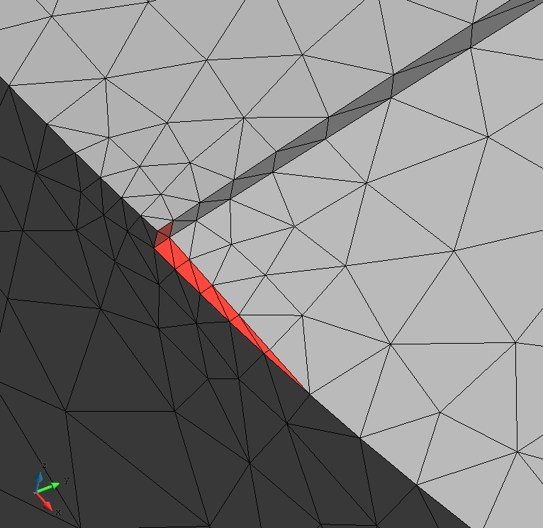
In the following figure a detail of the mesh in that region is shown, when the option Skip entities automatically is not set (don't skip any entity).
Let's try to skip these entities:
- Select Mesh criteria --> Skip --> Lines in the Mesh menu, and select the lines 234 and 235. Click ESCAPE to end the selection.
- Select Mesh criteria --> Skip --> Points in the Mesh menu, and select the points 37 and 184. Click ESCAPE to end the selection.
- The Draw --> Skip entities option of the Mesh menu can be used in order to see graphically the entities that will be skipped or not when meshing.
- Ensure the option Skip entities automatically is not set in the preferences window, and generate the mesh with 9 as the general mesh size. A zoom of the resulting mesh in the area of interest should be like the following one.
|
|
| Detail of the mesh in the zone of interest without skipping entities automatically. | View of the mesh generated skipping only the selected lines and points. |
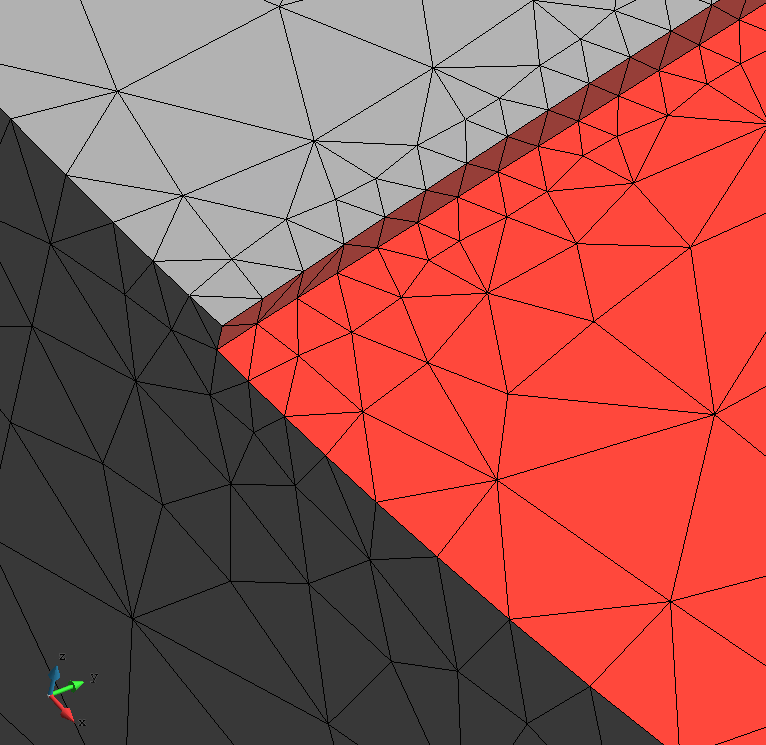
As can be seen, now the mesh is different, as the lines and points selected are not meshed (switch between geometry and mesh mode to see were the lines 253 and 254 are located with respect to the triangles).
Chordal error
The chordal error is defined as the distance between the mesh elements and the geometrical model. In planar regions, for instance, its value is always zero, but in regions with curvature the chordal error increases as the element size gets higher.
Depending on the characteristics of the model and the simulation requirements, it may be interesting to assign sizes to the geometrical entities according a given maximum chordal error, or let GiD refine the regions of the model with higher curvature in order to accomplish it.
In this section it is explained how to take care on the chordal error when generating meshes with GiD.
Assign sizes by chordal error
The option of assigning sizes by chordal error criteria is useful when the geometrical entities (lines and surfaces) have more-less the same curvature within all the entity.
By using this option, GiD computes automatically a mean curvature of the whole entity and assigns a mesh size to that entity which accomplishes with the chordal error defined considering the curvature.
In order to see an example, open the GiD model gid_model_basic_course.gid from the folder where the material of the course is. Hereafter, a figure of this model is shown:
View of the model used in this part of the course.
Mesh using automatic parameters
First of all, let's see an example of mesh using the default meshing parameters of GiD.
- Select Reset mesh data from the Mesh menu, to ensure the mesh will be generated using default parameters.
- Open the Preferences window, and set the Default values in the Meshing branch. (remember to select all subbranches within the Mesh branch, right click and select Default values on selection) Then click Apply and close the Preferences window.
- Generate the mesh using 10 as general size. The following mesh should be generated:
View of the mesh generated with GiD default values and a general mesh size of 10.
As it can be seen, this mesh is probably too coarse in the thin cylindric volumes, but it may be ok for the planar shapes.
Mesh with sizes assigned
We are now going to assign better sizes to the surfaces and lines of the model, so as the final mesh size will be guided by a given chordal error criteria.
- Select the option Unstructured --> Sizes by chordal error... from the Mesh menu. The following window should appear:
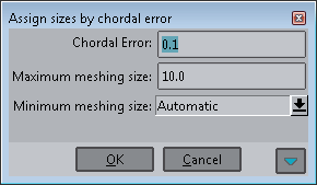
In this window user can enter the absolute value of the chordal error allowed, and the maximum and minimum mesh size. To get an idea of the corresponding element size given by a chordal error, user can expand the window by clicking on the down-arrow button in its right-lower part (beside CANCEL button):
- Expand the window and click on the line-icon button of the right-lower part of the window. Then select some curved line of the model. If you click, for instance, on the line 113, the following values appears in the window:
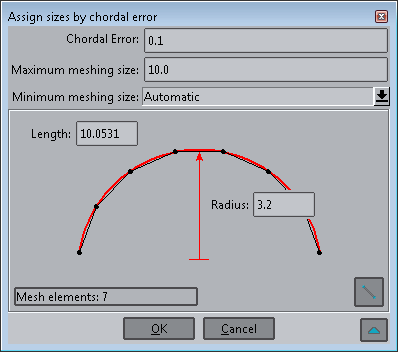
Now we see that with a value of 0.1 as chordal error, 7 elements will be created in the line 113.
- Click OK in the window. Now GiD has assigned automatically a mesh size to the lines and surfaces of the model, trying to accomplish with the chordal error specified by the user.
- Select Draw --> Sizes --> Surfaces from the 'Mesh' menu. Then the sizes assigned can be seen onto the model as shown in the following figure:
View of the sizes assigned automatically by GiD considering a given chordal error.
Note that the planar surfaces have no size assigned, as they have no curvature.
- Set RSurf as the unstructured surface mesher in the Meshing --> Structuration type branch of the Preferences window. This mesher tends to give better quality meshes than RFast one.
- Generate the mesh (Ctrl-g) with 10 as general size, and see the result:
Mesh generated with the sizes assigned automatically by GiD, following the maximum chordal error allowed specified by the user.
Note that this final mesh has smaller mesh size in some geometrical entities, but each geometrical entity is meshed considering a single size for the whole entity.
Smoothing options
In the Meshing --> Other branch of the Preferences window, user can find the Smoothing option, inside the Others group. These possibilities are:
- Normal
- HighAngle
- HighGeom
The first option performs a standard Laplacian-like smoothing algorithm. The second one tries to improve more the quality of the mesh elements in terms of angle.
The third option (HighGeom) is the interesting one when trying to minimize the chordal error of the mesh generated. If user set this smoothing preference, the final smoothing of the mesh will try to minimize the chordal error of the elements, but this may give a worse quality elements.
To see how this option works, let's see an exaggerated example of this using the model gid_model_basic_course.gid.
- Open the model gid_model_basic_course.gid.
- Select the Reset mesh data option from the Mesh menu.
- Set the Default values in the Meshing --> Other branch of the Preferences window. To set the Default values in all the branches of Meshing, you should select all of them, click the right mouse button, and set the Default values on selection option. Then click on Apply.
- Then set RSurf as surface mesher in the Meshing --> Structuration type branch, and set HighGeom as Smoothing parameter in the Meshing --> Other branch.
- Generate the mesh (ctrl-g) of the model with a general size of 10. The resulting mesh should look like the following one:
View of the mesh using a large mesh size and the HighGeom option for the smoothing.
Although the mesh has a big chordal error, comparing this mesh with the one obtained with the default parameters (see section Mesh using automatic parameters of the course), user can see that the configuration of the elements tends to follow the curvature directions of the surfaces.
Chordal error to the whole model
Sometimes, rather than assigning mesh sizes to geometrical entities (the same size assigned to the whole entity), user may need to consider a chordal error criteria considering the whole model, independently on each entity. Let's see an example.
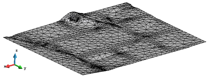
Open the GiD model 'model_chordal_error.gid' from the folder where the material of the course is. Hereafter, a figure of this model is shown:
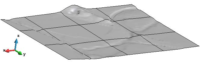
View of the geometrical model used in this course.
This model comes from a DTM (digital terrain model). One of the typical characteristics of this kind of models is the big size of the model in two directions (x and y in this example) compared with the other direction (z). This implies a specific meshing requirements in order to get the less number of elements without loosing accuracy in the geometry representation.
Chordal error to the whole model: Mesh using automatic parameters
Let's have a look at the default mesh provided by GiD if meshing with the default meshing parameters:
- Set the Default values in the Meshing branch of the Preferences window. (remember to select all subbranches within the Mesh branch, right click and select Default values on selection) Then click Apply.
- Select Generate mesh option from Mesh menu, and generate the mesh with the automatic size proposed by GiD. The resulting mesh should look like the following one:
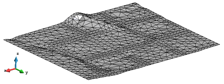
Mesh of the model with the automatic meshing parameters of GiD.
This mesh could look reasonable, but if we focus on some regions of the model, we see that some parts of it are not represented by the mesh because they are smaller than the element size. However, we see that these parts are localized in specific regions of the model. The rest of the model is well represented by this mesh.
We could try to generate a finer mesh of the model to capture the geometrical details, but this should lead to an excessive number of elements. Try to generate the mesh with a general size of 4. In the next figure the resulting mesh is shown:
 Mesh of the model with a general mesh size equal to 4.
Another option could be to assign a smaller size to the surfaces which have the details to be preserved, but it can be seen that those details do not cover the whole surface.
Chordal error options
User can control some parameters in order to apply the chordal error criteria to the whole model (not to specific geometrical entities). This parameters can be set at the Meshing --> Chordal error of the Preferences window:
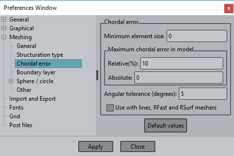
View of the Meshing --> Chordal error branch of the Preferences window.
There are three parameters which controls the maximum chordal error allowed in the model:
- relative: this value is the chordal error of an element divided by its characteristic size.
- absolute: this value is the chordal error itself.
- Angular tolerance: this value is the deviation between normals of adjacent entities.
The parameter Minimum element size allows the user to define the minimum size for the mesh elements. Trying to accomplish the chordal error criteria, GiD may generate too small elements in some regions, so this parameter may be interesting sometimes.
The checkbox Use with lines, RFast and RSurf meshers indicate that these parameters will be applied when using these meshers. Otherwise, they will only be considered in MinElem mesher (this mesher is explained in detail in section MinElem mesher).
Mesh following chordal error chriteria
Let's use a chordal error criteria in order to let GiD refine the mesh in the regions with higher curvature.
- Open the Preferences window.
- Set the RSurf as the surface mesher (as told in previous sections of the course, under Preferences --> Meshing --> Structuration type, RSurf mesher, in general, trends to represent the original geometry in a more accurate way).
- Set the Use with lines, RFast and RSurf meshers option in the Meshing --> Chordal error branch, and set to 10% the relative value of the Maximum chordal error in model, and an Angular tolerance of 5 degrees.
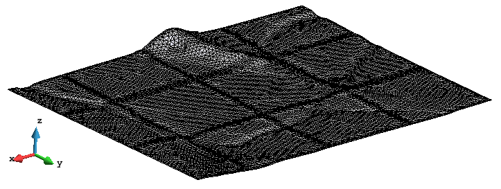
- Generate the mesh (ctrl-g) of the model using 15 as the general size. The resulting mesh should be like the following one:
Mesh of the model using RSurf mesher and 10% as the maximum relative chordal error allowed, and an angular tolerance of 5 degrees.
As it can be seen in the figure, the regions with higher curvature have a refined mesh.
MinElem mesher
The MinElem surface mesher is designed to generate as minimum number of elements as possible representing the shape of the geometry according to the given chordal error parameters. This kind of meshes are often used for visualization purposes, or in some parts of the model where the quality of the elements is not so important. Let's see an example:
- Open the Preferences window.
- Set the MinElem as the surface mesher in Preferences --> Meshing --> Structuration type.
- Generate the mesh (ctrl-g) of the model using 1000 as the general size; this high value will evidence the difference between the meshes generated with this mesher, as it only tries to preserve the chordal error, not trying to reach good quality elements in terms of angle. The resulting mesh should be like the following one:
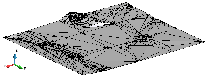
View of the mesh generated with MinElem mesher.
Changing the chordal error settings in the Preferences window, it can be appreciated how the mesh is adapted to the geometry depending on them. In the following Figure, for example, the resulting mesh using 2 degrees as angular tolerance is depicted:
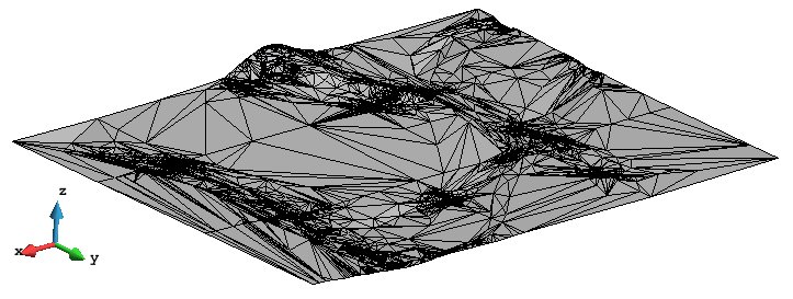
View of the mesh using MinElem mesher, 10% as Relative maximum chordal error, and 2 degrees as angular tolerance.
Force points to mesh
The geometrical definition inside GiD follows a hierarchical approach: a line must have points in its ends (or one point if it is a closed curve), a surface must be surrounded by lines, and a volume must have a closed collection of surfaces as a contour. This topology is automatically passed to the mesh; for instance, the nodes of a line's mesh are nodes of the mesh of the surfaces containing that line.
In some situations, user may need to force a mesh to have a node in a given position of space. GiD includes this functionality for surface and volume meshes.
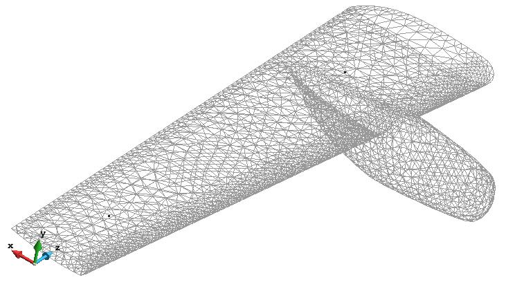
In the following example we will use the model model_course_forced_points.gid, shown in the following figure ( View --> Render --> Normal). The model represents an aircraft wing.
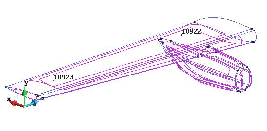
View of the model used in this course.
In the figure two points can be appreciated (labeled as 10922 and 10923). These points are not belonging to any higher order geometrical entity (it can be seen using the View --> HigherEntity --> Points functionality).
Let's generate a mesh of the model:
- First of all reset all meshing settings: open the Preferences window, select all subbranches within the Mesh branch, right click and select Default values on selection; then click Apply and close the Preferences window.
- Generate a mesh (ctrl-g) using 100 as the general mesh size, setting the option Get meshing parameters from model. This option uses most of the meshing parameters used the last time the model was meshed. The resulting mesh should be as follows:
Mesh of the model using 100 as general mesh size.
If we zoom the zone were the isolated points are, we can see that that points have generated isolated nodes, which are not connected to the surface mesh.
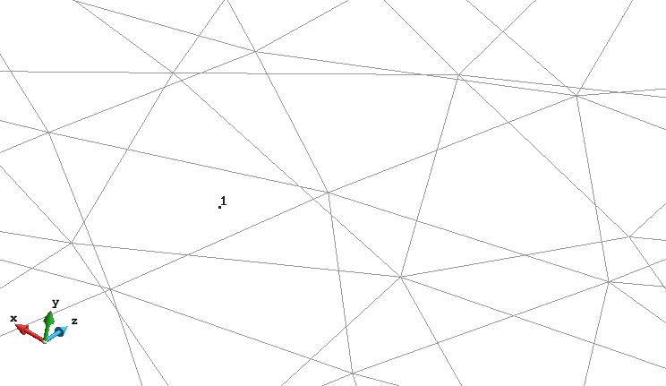
Zoom of the zone of the mesh where it can be seen that the node 1 (comming from the point 10923 of the model) is isolated.
Mesh with forced points
To force that two points to own the mesh of a surface, user may follow these steps:
- Select Mesh criteria --> Force points to --> Surface mesh in the Mesh menu.
- Select the surfaces of the model and press <Esc> (steps to follow are indicated in the command line, in the lower part of GiD window).
- Then select the two points and click <Esc>. GiD will assign the closest surface (between the surfaces selected) to each of the points selected.
- Generate the mesh again, and you will see that now the surface mesh owns a node in each position of the points to be forced. (A useful way to check this is zoom in the area of interest and switch between Geometry and Mesh view mode, so as the position of the geometrical point can be seen.)
Boundary layer mesh
In some situations, the numerical simulation require anisotropic meshes. This kind of requirement is often associated to CFD codes, which need a big concentration of elements in some areas following the direction in which the velocity of the fluid changes rapidly (high gradients of velocity). This anisotropic meshes are typically located in the contacts between fluid and solid in Fluid Structure Interaction (FSI) problems. This particular mesh receive the name of boundary layer mesh, and presents layers of very stretched elements near the solid wall. This virtual layers get higher as the distance to the solid wall increases.
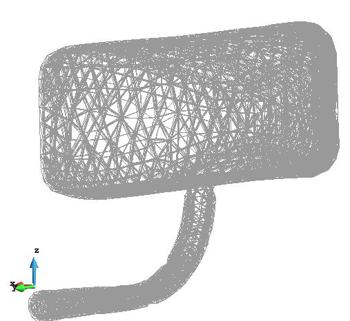
GiD is able to generate boundary layer meshes both in 2D and 3D. In this course we are going to generate a boundary layer mesh in 3D (volume elements) of the model model_course_blm.gid, which is a model of the rear view mirror of a competition car.
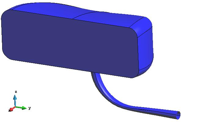
View of the model used in this course.
Switch on and off the layer named vol in order to see the control volume around the model.
Create 3D boundary layer mesh
We are going to generate a volume mesh of the control volume (in layer vol), and a boundary layer mesh around the rear view mirror (surfaces in layer mirror).
Switch layer vol on again.
Select Boundary layer --> 3D --> Assign in the Mesh menu, and select the volume of the model. Then click Escape, and the Boundary Layer Mesh window should appear:
|
|
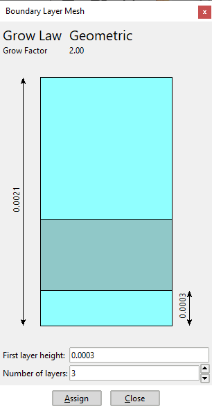
Generate the mesh (<Ctrl>-g) with general size equal to 0.0175, and using the meshing parameters from the model (check the corresponding checkbox in the window appearing when selecting generate mesh).
The resulting mesh has the boundary layer elements attached to the surfaces in the layer mirror. It can be seen that a new Layer has been created inside GiD named BLM. This layer contains the different boundary layer meshes of the model. It is useful to see separately the boundary layer mesh from the isotropic one. If user doesn't want to get the boundary layer mesh in a separated Layer of GiD, the option can be set in the Meshing --> Boundary layer branch of the Preferences window.
|
|
Embedded mesh options
In this section, some options of the embedded mesher are shown. The model gid_embedded_example_lamborgini.gid is used in this course, which is a geometrical model of a car inside a control volume, as shown in the following figure:
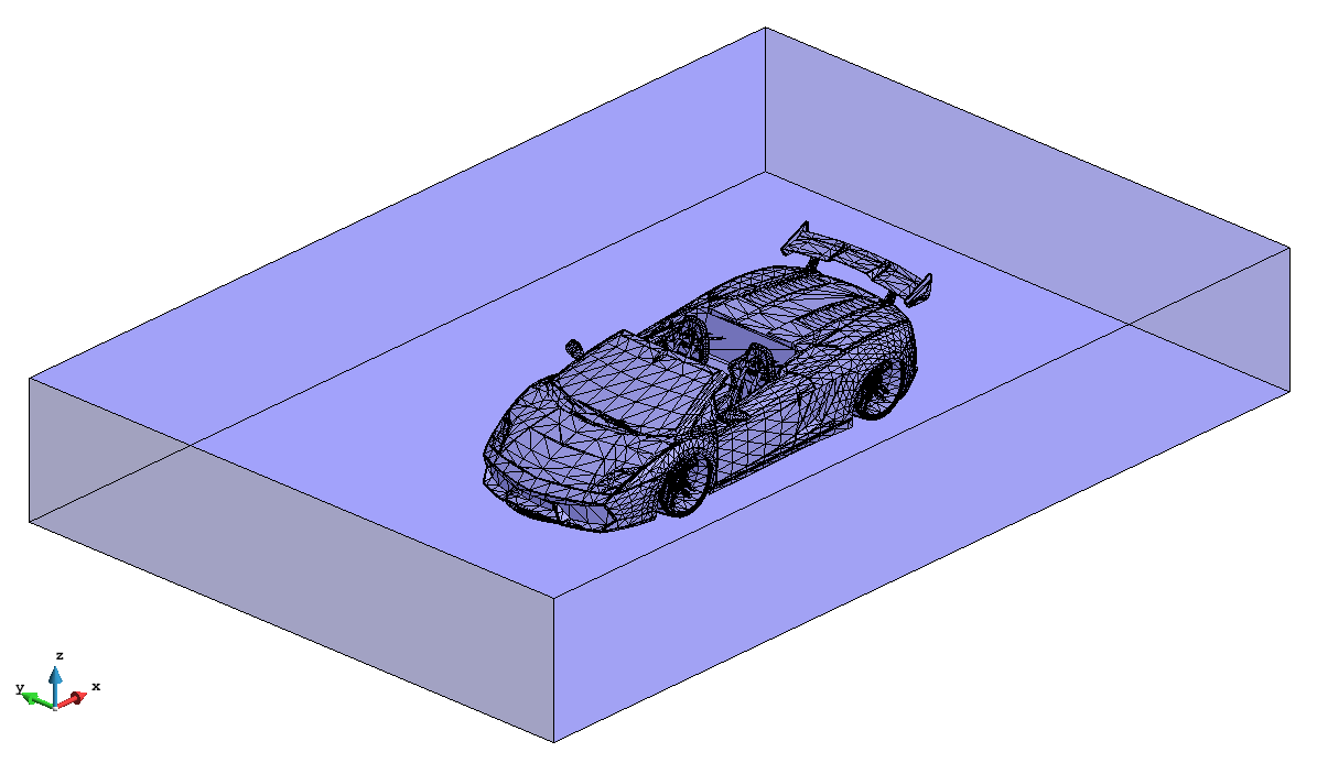
View of the model used in this course.
This embedded model consists in a prismatic volume (the calculation volume), and the embedded region formed by the surfaces defining the car. Note that the embedded region must enclose a part of the space, but it is not needed to be watertight. As it can be seen in the following figure, some of the higher entities of the lines of the car are not 2 (which is the condition to be watertight):
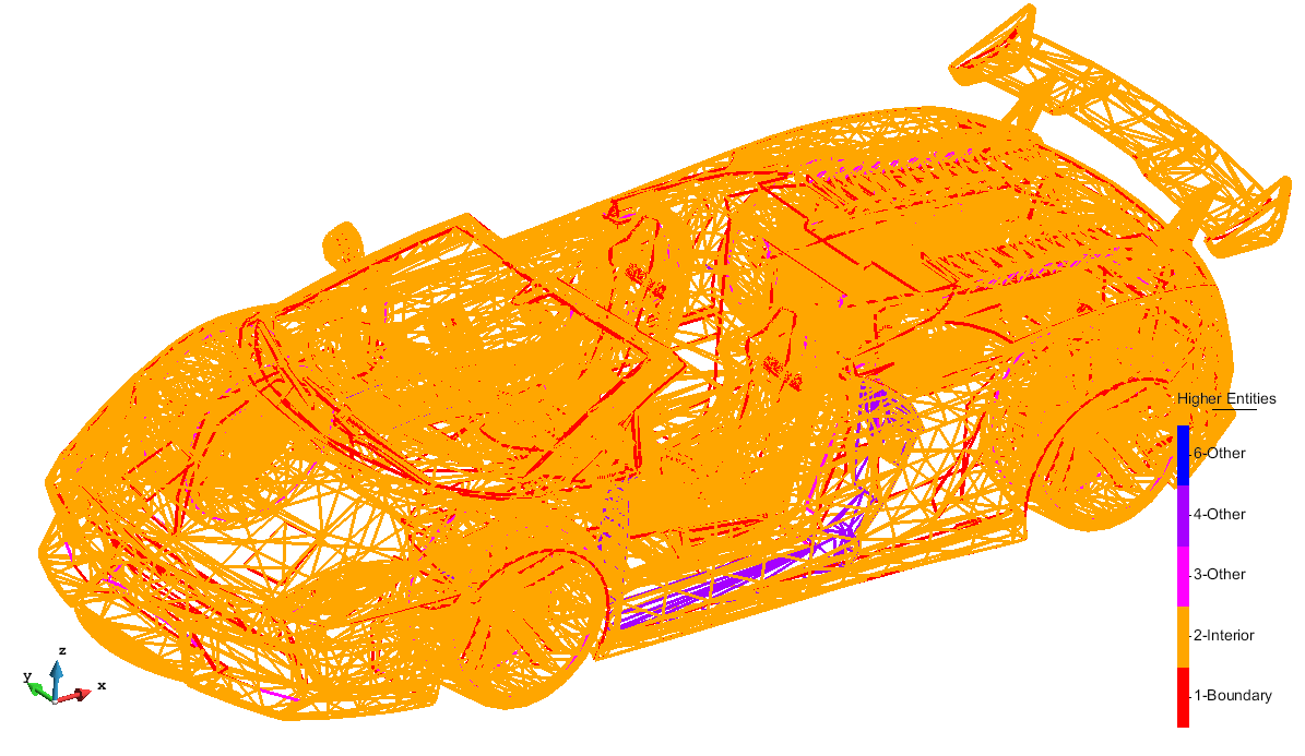
Higher entities of the lines belonging to the surfaces defining the car.
First of all, select the Embedded mesh type in the Meshing --> General branch of the preferences window, and a size transition factor of 1. in order to be faster generating the mesh.
Then, generate the mesh of the model (Mesh --> Generate), using a general mesh size of 20. The following mesh should be generated:
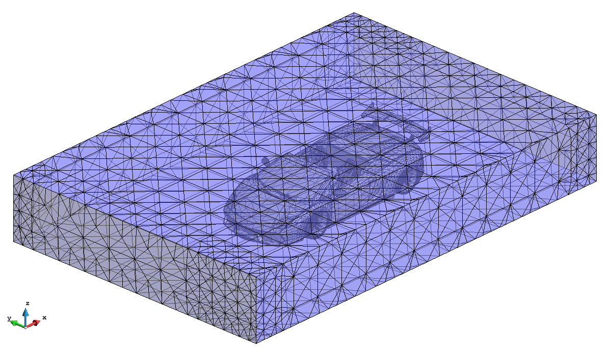
View of the mesh generated
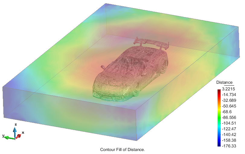
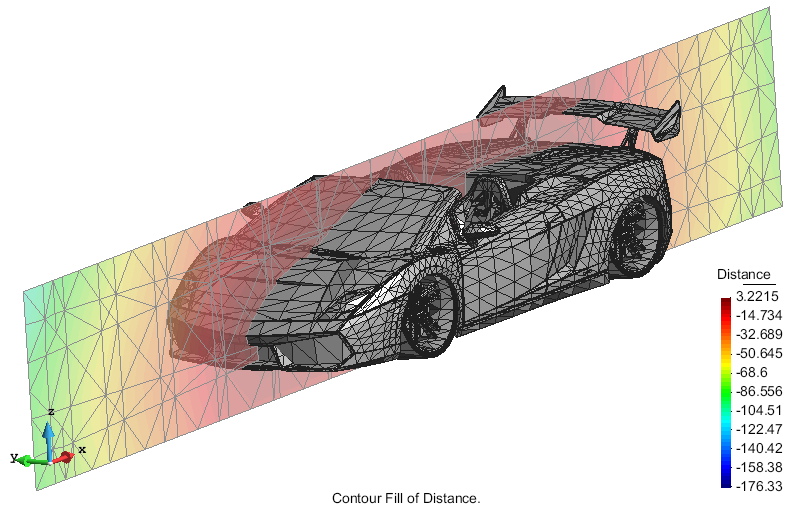
Going to the post-processing part of GiD, we can see that a result has been created automatically with the signed distances on the nodes. In the following figures the contour fill of distances on the mesh and onto a cut can be appreciated:
Contour fill of distances on the skin of the calculation volume mesh. |
Contour fill of distances on a cut plane. |
Remember to hide the result view on the car skin set |
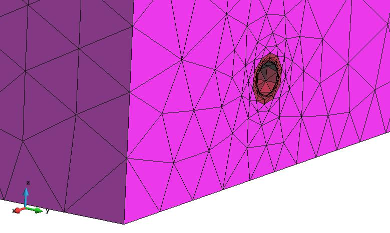
Having a look at the iso-surface of distance equal to 0 (which may represent the skin of the car) we see that is too coarse to represent it:
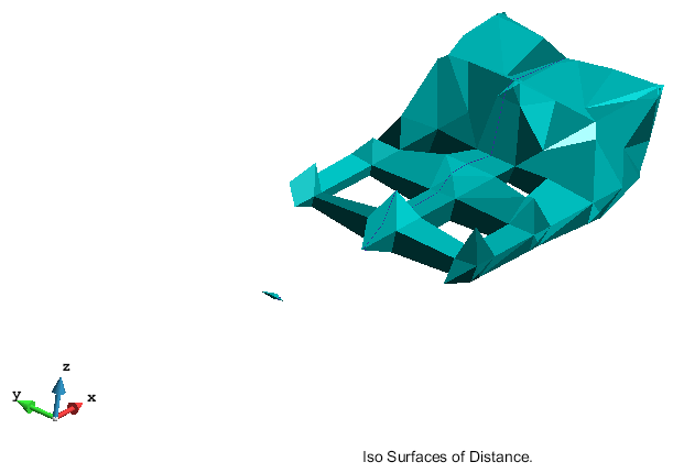
View of the iso-surface of distance equal to 0 with the mesh generated with size equal to 20.
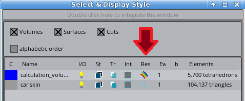
Assign mesh sizes
Assign a mesh size of 0.5 to all the surfaces of the car (Mesh --> Unstructured --> Assign sizes on surfaces) and generate the mesh again. Now, it can be appreciated that the mesh is finer near the skin of the car, so the iso-surface of distance 0 fits better to it:
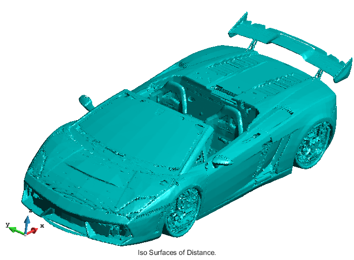
View of the iso-surface of distance equal to 0 with the mesh generated with size equal to 0.5 in the skin of the car.
Do not consider outer elements
In most cases, the solvers working with embedded meshes don't need the elements which all their nodes are out of the embedded region. You can unset the option Get outer elements in embedded meshes in the Meshing --> Other branch of the preferences window in order not to have this elements (this option is only available if Mesh type is set to Embedded in Preferences --> Meshing --> General). If so, the generated mesh has less elements, so some memory can be saved in the simulation process.
Considering the last mesh generated, for instance, the resulting mesh goes from about 9.3 Millions of tetrahedra to 6.7Millions. You can appreciate the mesh generated is not massive by moving the clip planes (View menu) to see its inner part in render flat mode.
COPYRIGHT © 2022 · GID · CIMNE