GiD - The personal pre and post processor
Advanced visualization tools
With this course you will learn how to manage the advanced visualization features present in GiD, available both in the pre and postprocessing parts.
Stereoscopic view
Model used
The model pyramid.gid is used in this example, which can be found at Material location.
Menu
View --> Advanced viewing settings...
Description
If you have an anaglyphic glasses you can try this option. The model can be set as an anaglyphic image in order to provide a stereoscopic 3D effect, when viewed with 2 color glasses (each lens a chromatically opposite color, usually red and cyan).
Anaglyphic images are made up of two color layers, superimposed. Since the glasses act as red and cyan filters we should be careful with the model's colors. To avoid problems we will change the contour fill color scale.
- From preprocess mode open the model
- Switch to postprocess mode
- In order to get a better view turn off the Layer0 and Layer8 layers
In order to test this option, first we will display a result with a given parameters in order to get a nice stereoscopic visualization.
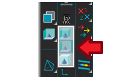
- Select the 12.5 step through View results --> Default Analysis/Step --> RANSOL --> 12.5 or clicking on

- Select View results --> Contour Fill --> Pressure (Pa)
- Select Utilities --> Set contour limits --> Define limits... through the menu bar or clicking on

Choosing the first option the Contour Limits window appears. With this window you can set the minimum/maximum value used for Contour Fills.
1. Check the Min checkbox and change the value to -0.2.
2. Click on the Apply button and Close the window.
3. Open the Preferences window, and go to the Postprocess --> Contour fill and lines branch. There, set the Color map to 3D Anaglyphs 2, and click Apply.
4. The Stereoscopic visualization settings, as well as other advanced ones, are centralized in the View --> Advanced viewing settings... window. Open it.
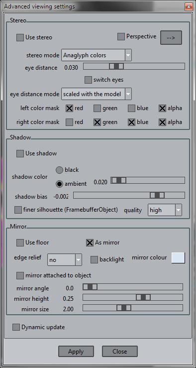
5. Check the Dynamic update option (from the lower part of the window) in order to change the options without the need to click the Apply button.
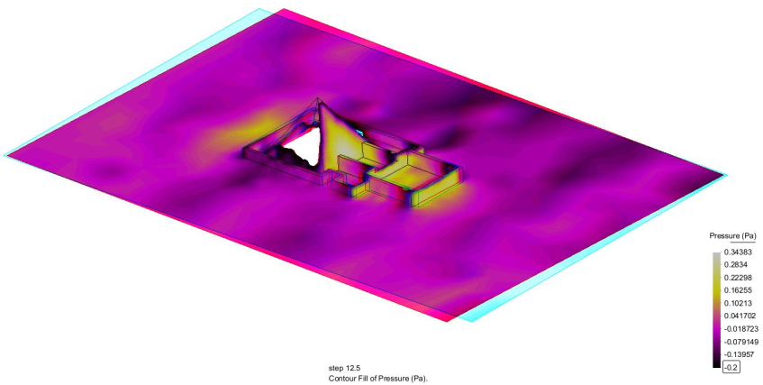
6. Check the Use stereo option, and change the eye distance to the value where you can see the 3D effect properly. The image should look like this:
Let's restore the visualization settings for the next points of the course:
7. Uncheck the Use stereo option and Close the window.
8. Set the Default values in the Postprocess --> Contour fill and lines branch of the Preferences window.
9. Select View results --> No Results
Mirror effect
Model used
The model Ferrari_Maranello_2002_visualization.gid will be used in this example, which can be found at Material location.
Menu
View --> Advanced viewing settings...
Description
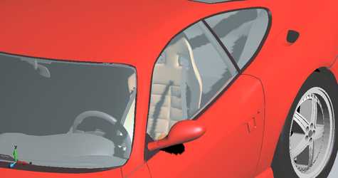
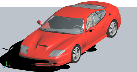
With this option enabled the model is mirrored on a ground surface, or it his ground plane can be used as floor (shadows are drawn on it).
1. From preprocess mode open the model.
2. Change the render mode selecting View --> Render --> Smooth. It can be seen (checking the other render modes) that the model is represented by a mesh.
3. Open the View --> Advanced viewing settings... window, and set the Dynamic update option in the lower part of it.
4. Look for the Mirror section of the window, and check the Use Floor option and a ground surface will appear under the model.
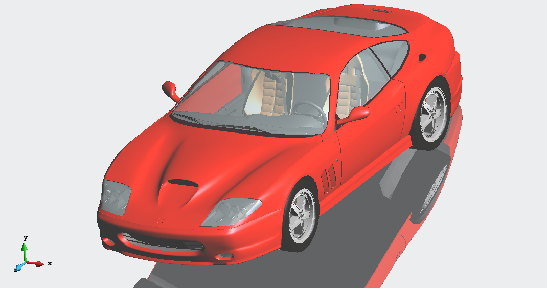
5. Check the As mirror option in order to get the model reflected in this ground surface.
6. Check the backlight option to get a better view
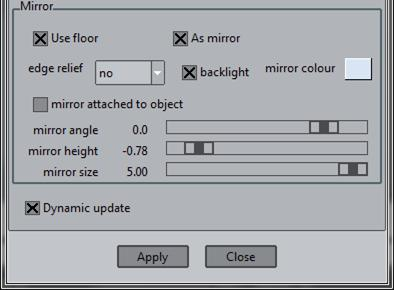
Several options can be set in order to get a better view of the reflection:
- Mirror angle: Changes the inclination angle of the ground
- Mirror height: Changes the height of the floor, relative to the object
- Mirror size: Changes the size of the ground
7. Play a little bit with these options until you get the desired view:
Shadows
Models used
The models Barcelona_for_shadows.gid and Ferrari_Maranello_2002_visualization.gid will be used in this example, which can be found at Material location.
Menu
View --> Advanced viewing settings...
Description
Shadows provide not only a better depth perception of the floating objects, but also provides more realism to the viewed model and results.
The technique used inside GiD to create shadows is called shadow mapping, in which:
- first, a shadow map is created by rendering the scene from the light's point of view;
- then, the scene is rendered from the user's point of view by checking whether the pixels is in shadow or not:
- pixels which are directly lit are drawn as always;
- pixels in the shadow area are drawn in black or with a dimmed ambient light.
With shadows enabled the scene is rendered at least twice, and sometimes three times, on some hardware and drawing the shadowed area with dimmed ambient light.
The shadow map is created for the whole model and not just the zoomed area. To minimize the staircase effect on the border of the shadows, the finer silhouette option can be used with different qualities.
Note: using shadows will slow down the frame rate of the visualization.
Note: the shadow map is a type of image which is stored in the graphics card, besides the visualized mesh information; selecting a too high quality for the finer silhouette, may result in a very poor performance, or even crash the program, if the memory of your graphics card is too low.
Shadows can be enabled through View --> Advanced viewing settings... which will pop-up the window with the shadow options.
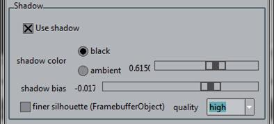
Options
- Use shadow enables or disables the shadows visualization;
- shadow color this option controls if the shadows should be black or should be drawn with a dimmed ambient light.
- shadow bias this options allows the user to adjust the offset between the occluder and the shadow, the default value is -0.002;
- finer silhouette this advanced option allows the user to control the granularity of the shadow, i.e., the resolution of the texture to be used to create the shadow. By default, i.e. deactivated, the same graphical window is used to created the shadow texture. An accelerated OpenGL 2.0, or the frame-buffer object extension is needed for this option to be used. If checked, the options are:
- medium which uses a texture of 1024 x 1024 pixels to create the shadow map, using 4 MB of memory on the graphics card,
- high which uses a texture of 2048 x 2048 pixels to create the shadow map, using 16 MB of memory on the graphics card,
- very high which uses a texture of 4096 x 4096 pixels to create the shadow map, using 64 MB of memory on the graphics card,
- highest which uses a texture of 8192 x 8192 pixels to create the shadow map, using 256 MB of memory on the graphics card.
Note: medium and high qualities may work with all king of graphics cards, even in Linux software mode, safe mode; but check the memory of your graphics card before choosing the very high or highest qualities for shadows. For these two last qualities, the graphics card should at least have 512 MB of memory.
Shadows Requirements
To get the best experience the user should check if GiD uses the graphics card or not. This can be done by looking the graphics acceleration icon at the lower right of the main window (a lightning):
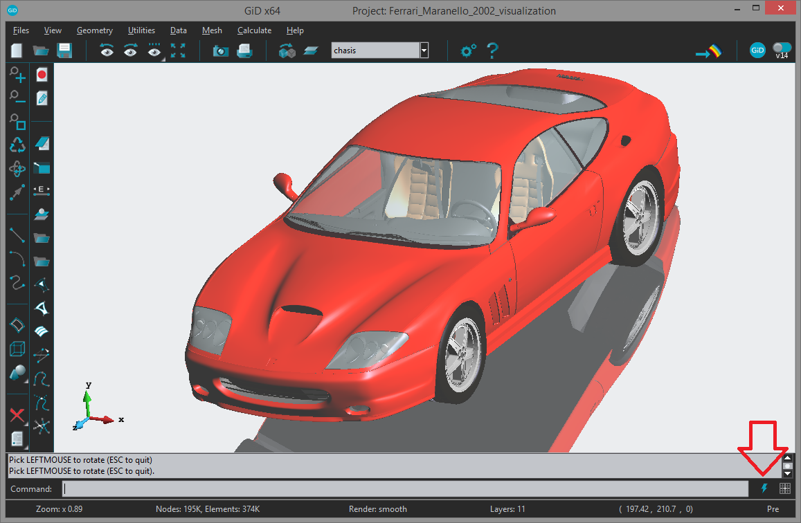
The blue lightning icon in the lower right part of GiD window indicates that the graphics card is used to accelerate the visualization.
The graphics configuration can be changed by clicking on this icon, which opens the following window:
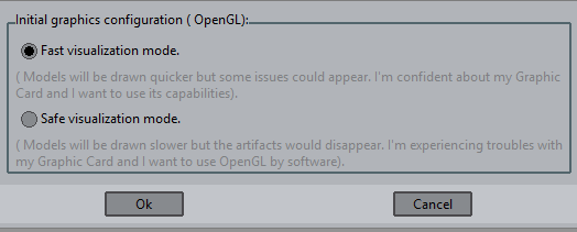
or at the Graphical --> System branch of the Preferences window under OpenGL options.
Window users
To use shadows GiD requires at least OpenGL version 1.5. The OpenGL version can be checked at Help --> About:
System information about the graphics can be found pressing the More button in the Help --> About window. Scrolling down, the OpenGL version can be checked.
Linux users
In Linux, the software mode of GiD uses the [Mesa 3D] library, an open source implementation of the [OpenGL] specification, which provides at least OpenGL version 2.1.
Shadows parameters
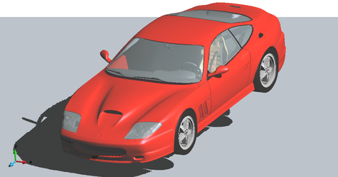
Open the Ferrari_Maranello_2002_visualization.gid model from the Material location. It has to be noted that the visualization results depends strongly on the graphical card of each computer, so it is common not to get the same visualizations than the ones shown in this course.
1. Select View --> Advanced viewing settings...
2. Enable Dynamic update option in the lower part of the window to avoid clicking Apply button after each parameter setting. Enable Use shadow option and select black as shadow color (you may change the shadow bias parameter in order to calibrate your visualization). When zooming, it can be appreciated that the border of the shadow shows a staircase effect.
|
Zoom where it can be appreciated the staircase effect |
3. Enabling the finer silhouette option and setting different qualities it can be appreciated how the shadows visualization improves. Also, setting the 'ambient' shadow color results in a more smooth visualization.
Improved shadows visualization with finer silhouette with very-high quality |
Zoom view ('cristal' Layer on) of the improved shadows visualization |

Shadows: Change light direction
Using the option Render --> Change light dir of the contextual menu, the direction of the light, and thus of the shadow, can be interactively changed.
Open the model Barcelona_for_shadows.gid to see the effects of this. This model represents part of the city of Barcelona, including the 'Sagrada Familia'.
Setting the shadows options and changing the light direction nice visualizations can be obtained, as the ones shown in the following figures.
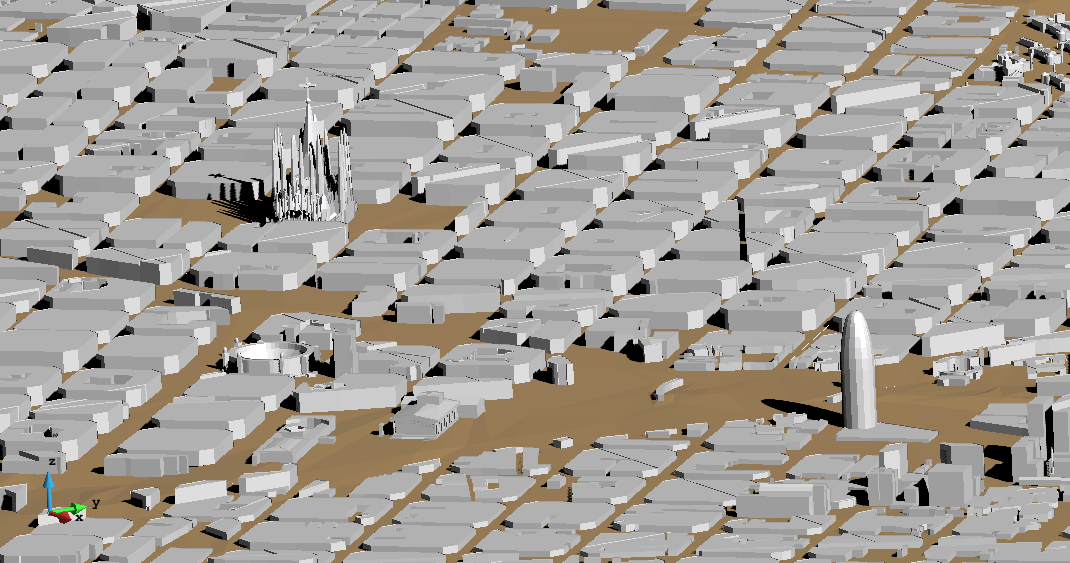
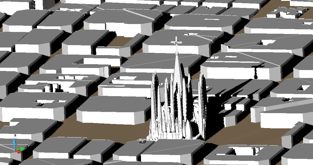
(Check that 'shadow bias' are at -0.001 and finer silhouette on)
Shadows: Example with streamlines
As it has been pointed out, all the visualization features of GiD can be applied both to the pre and the postprocessing part of GiD.
Let's see an example of useful shadows to demonstrates better depth perception of the created streamlines: which ones are near the ground and which ones not.
- Open the pyramid.gid model, and switch to the post-process mode in GiD.
- Select Files --> Import --> Stream lines... and choose pyramid.flavia.streams.msh located in pyramid.gid.
Using shadows, the height of the stream lines are better perceived than without.
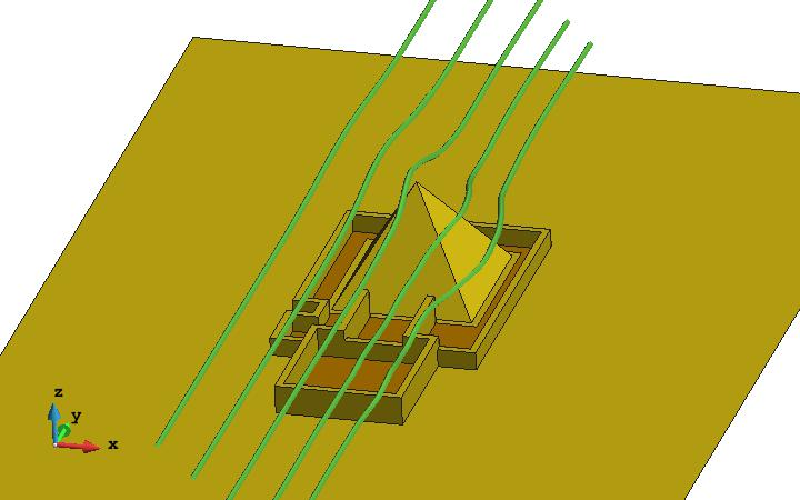
stream lines without shadows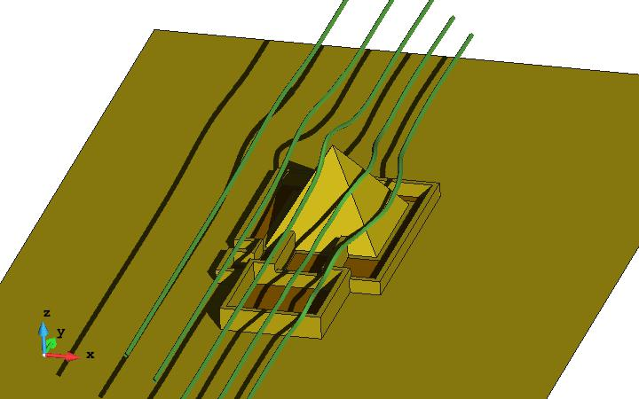
shadows helps to perceive the relative position of the streamlines
Advanced visualization tools: Combining pre and postprocess models
You can also combine the visualization of the geometry o preprocess mesh and the postprocess results. Here is an example.
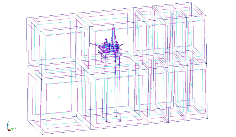
Geometry of the platform_small project.
This example is a simulation of waves against a oil platform. The model platform_small.gid can be found at Material location.
- open the platform_small.gid project,
- go to postprocess,
- select the menu Geometry --> Extract boundaries;
- select All lines display style;
create a new set by selecting elements of the platform (using the Send to --> new set option of the Display style window), change its color and switch it off;
- create a new set by selecting elements of the columns (using the Send to --> new set option of the Display style window), and change its color;
use culling to show the interior of the volume:
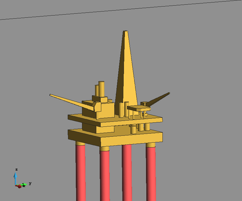
The single triangle mesh of the volume boundary has been separated in the grey box triangle set, the golden platform and the 'middle red' columns.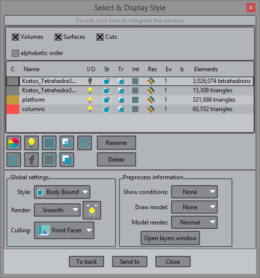
Listing the new created mesh sets. On the right, enabling the culling of the front faces.switch all surface sets on and enable the culling of the font faces.
switch off the platform set, enable the visualization of the preprocess mesh, using the smooth render:
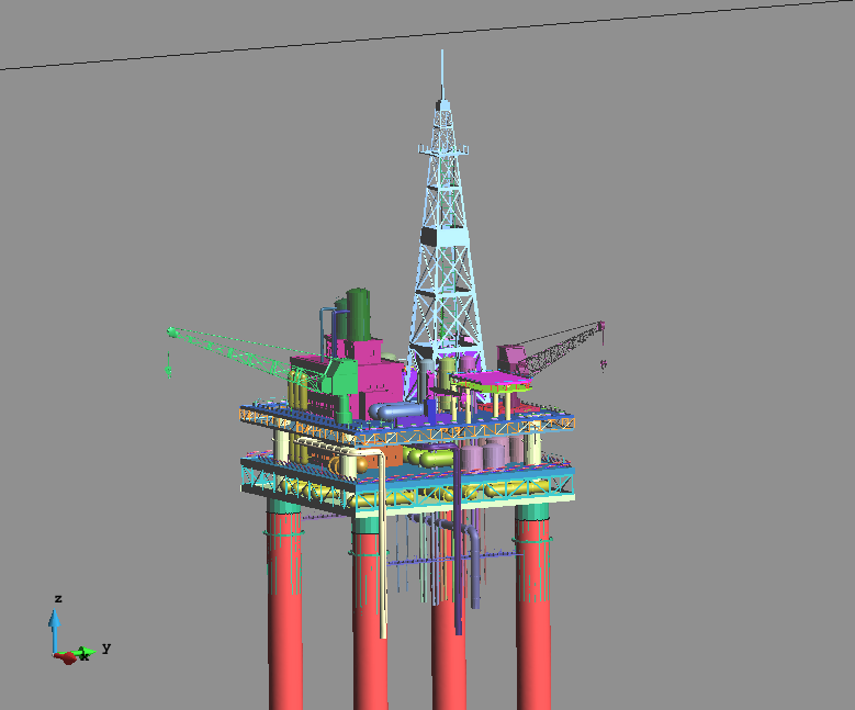
Visualizing both the preprocess and the postprocess mesh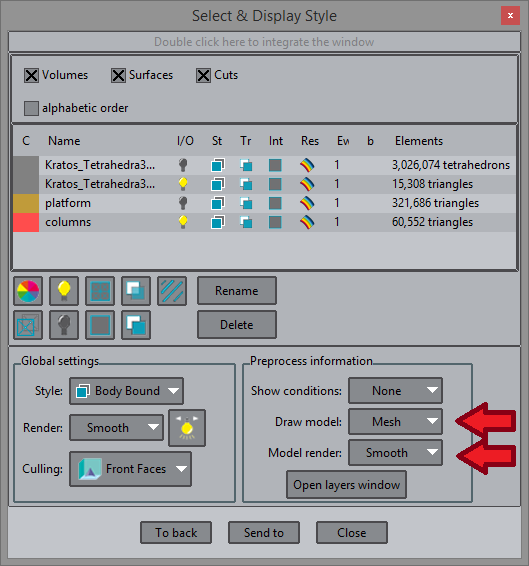
Enabling the visualization of the preprocess mesh, smooth render
- Now set the 'grey box' mesh style to boundaries, and turn off the culling.
Do an iso-surface of DISTANCE with value 0.0, and make its color blue-sky:
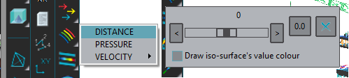
Creating the iso-surface with value 0.0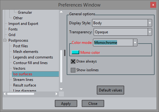
Setting the iso-surface color to blue.
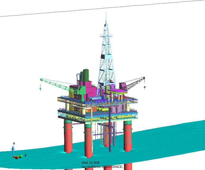
Animate the result with the Windows --> Animate window
The achieved result is shown hereafter:
COPYRIGHT © 2022 · GID · CIMNE