GiD - The personal pre and post processor
Working with large models
- Enrique Escolano
- Jorge (Unlicensed)
- Abel Coll Sans
About Result's cache
Results' cache is a mechanism implemented in GiD which allows to analyze huge results files which do not fit in memory. The whole mesh model resides in memory but only the results used to render a contour fill, iso-surfaces, etc. are loaded in memory, in a user defined pool.
First this mechanism is explained in detail, including some considerations and limitations, and then an examples shows the benefits of this mechanism.
Result's cache: How it works
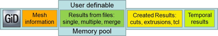
Results cache block diagram
The Result's cache mechanism allows the analysis and visualization of lots of results which, otherwise, could not be held entirely in memory.
Instead of loading all results from the file(s), a certain amount of memory, a memory pool, is reserved and used to load and unload the result values as they are needed.
When this mechanism is enabled, with the indexed options enabled, and a result's file is opened for the first time, GiD verifies the correctness of the file and gets some information about the results, such as minimum and maximum values, amount of memory needed, position in file; and this information is stored in the index file. The next time the same result's file is opened, only the index file is loaded, reducing the load time considerably. But no results are loaded, they are loaded only on-demand.
If the indexed options are off, then no index file is created or read, and so the parsing of the result's file is performed each time it's opened, but no results is loaded in memory. They are loaded on demand.
If a result is selected to do, for instance, a contour fill visualization and their values are not in memory, then GiD checks if there is enough space in the memory pool and loads them. If their values are already in memory, the time-stamp of the result is actualized.
If there is not enough space in the memory pool to load the desired result, then the oldest results are unloaded, and their memory freed, until there is enough memory to load the desired result.
What's cached: Only results which are already stored in files are cached, i.e. files read with Files --> Open, Open multiple or Merge.
What's not cached: When cuts, extrusions are done or iso-surfaces are converted to full featured meshes, the generated results are held in memory. Results created in GiD using the Window --> Create result, Create statistical result are held in memory. Also results imported using Files --> Import or using the plug-in mechanism or the TCL procedure GiD_Result create ... are held in memory too.
In order to cache these results, save the model, with Files --> Export --> Post information --> whole model / HDF5 GiD post and open it again.
Result's cache options:
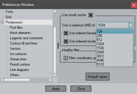
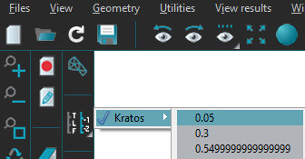
- The user can enable the Result's cache in the Post files panel of the Utilities --> Preferences window. If you change this setting you'll need to read the post-process file again.
- The size of the memory pool can also be adjusted by selecting one of the predefined memory sizes or entering the desired amount in the same entry. The size can be adjusted according to not only the amount of memory the computer has, but also the memory used by a single result. You may change this value during your session.
For instance, a mesh with one million nodes with a vector result at each step, the amount of memory needed to hold the nodal vector result of a single step will be: 4 components ( x, y, z and modulus) * 4 bytes per float * 1 million nodes = 16 MBytes of memory. If there are 100 steps in the analysis,, to get a fluid animation. the memory pool must be set to 16 * 100 = 1.6 GBytes of memory. But if the animation is of a contour fill or an iso-surface of a scalar result, then the amount of memory needed is reduced by 4, to 400 MBytes.
Other interesting options to save loading and access times from huge files are:
- Use indexed binaries: will speed up the access of the results on huge file, more over if the user access them randomly. It only applies to raw binary result files, not to hdf5 gidpost files.
- Use indexed results information: stored in the indices, will speed up the loading of huge results files, as the results information, except values, are already stored in the index files.It only applies to raw binary result files, not to hdf5 gidpost files.
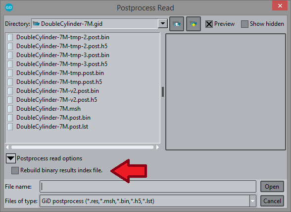
Note: The index of the results' file is automatically created for raw binary postprocess files, if it does not exists or if the results' file is newer than the index file. HDF5 GiDPost files do not need an index file. If for any reason GiD has problems reading the index file, or the information stored in this file is not actualized, the user can recreate these index file in the File --> Open dialog box, under the Postprocess read options:
Caution
When the result's cache is used, the result's files remains opened, to make the retrieval of the results faster.
If a simulation is done on a cluster where the model is partitioned in 1024 pieces and 1024 separated result's files are generated, when these 1024 result's files are merged in GiD with the result's cache mechanism enabled, then the 1024 files will still be opened!
Usually in Linux the maximum number of opened files are, precisely, 1024, and some of them are already used, causing GiD to display an error when the user tries to merge these 1024 result's files.
This limit on the number of open file descriptors is one of the limits imposed by the system, like the cputime, coredumpsize, datasize, etc. There are two types of limits in Linux, soft limits and hard limits. Usually the soft limits can be changed by the user, but administration privileges are needed to change the hard limits.
Sometimes soft and hard limit are not the same, and the user is able to raise the number of open file descriptors to its hard limit. If the user uses the bash shell, then the commands ulimit -Sn ( open files soft limit) or the ulimit -Hn ( open files hard limit) should be checked. An additional parameter can be entered to modify the limit, for instance ulimit -Sn 2048. In csh/tcsh the command is limit [ -h] openfiles
Result's cache Example


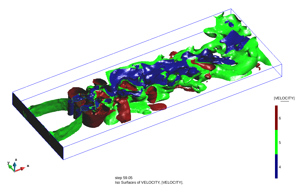
DoubleCylinder-7M snapshots.
This example is a simulation of the flow around two 3D cylinders. The model DoubleCylinder-7M-v2.post.h5 can be found at Material location, as it is a big model, it may not be in the USB memory stick, but in the ftp server.
Loading the model in GiD with the result's cache disabled, more than 2 gigabytes of memory will be used, making it difficult, if possible, to view it and work with it on a 32 bits platform.
To make sure the model can be loaded and handled in GiD with a 32 bits operating system, the results cache should be enabled, and the memory pool should be set to 128 MB before loading the model. With this results cache size, you'll be able to read the model using less than 2 GB of memory.
If you read the DoubleCylinder-7M-v2.post.bin file:
Enable the use of indexed binaries and indexed results information.
After the initial creation of the index file DoubleCylinder-7M-v2.post.bin.idx, the next sessions will open the model in less than 30 seconds, the time to read the mesh, create the graphical objects to visualize the mesh and read the results index.
If you read the DoubleCylinder-7M-v2.post.h5 file:
There is no need to use an index file, as the information is already inside the hdf5 file. It will take less than 45 seconds to read the mesh, create the graphical objects to visualize the mesh and get the results list.
After loading the model in GiD with these settings, in the task administrator can be seen that GiD has used less than 2 GBytes of memory, and is using around 700-900 MBytes of memory, depending on the file (.bin or .h5) and GiD version (32 or 64 bits).
1. First check in the Utilities --> Preferences window that the Result's cache is enabled and set to 128 MB.
2. load the Double Cylinder 7M example;
3. switch off the surface sets and let only the volume meshes on;
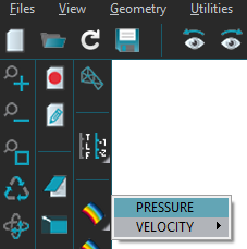
4. Select the first time step and do a Contour Fill of Pressure:
 |  |
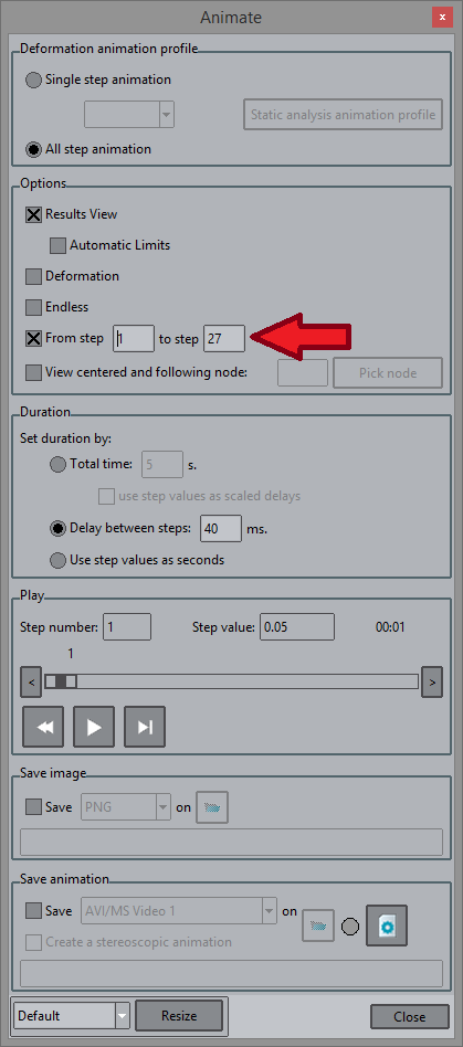
5. Open the Window --> Animate window, set the Options From step to 1 and To step to 27 and press the Play button:
6. Press the Rewind button and play it again.
You'll notice that the first time it takes some time to draw the result at each time-step. This is so, because it read the result from the file and then renders it. The second time the Pressure result for each time-step is already in memory and thus the animation is quicker. Check the Task manager to see how much memory GiD is using.
- Now increase the option To step to 32 and press the Rewind and the Play button.
You'll notice that the first 27 animation steps are done faster and that the last 5 time-steps (from 28 to 32) is somewhat slower. This is because it read the Pressure result from file.
If you press the Rewind button and play the animation again, you'll notice that the animation is slow, i.e. not as fast as when we're doing the animation from step 1 to 27 !
This is because of the size of the Result's cache:
- Check the number of nodes of the model with Utilities --> status. You'll see that the model has 1,208,206 nodes.
- For the Pressure result, which is stored as 4-byte float, this represents around 4.6 MBytes of memory.
- We have allocated 128 MB as results cache, which can hold 27 time-step of the pressure result.
- As we're animating 32 time-steps, GiD keeps freeing and reading all time-steps.
- Now increase the result's cache to 170 MB and do the animation from step 1 to step 32 again.
- You'll notice that now the animation runs faster as it has more memory to store the Pressure result
NOTE: be aware that if you use the Automatic Limits option of the Animate Window:

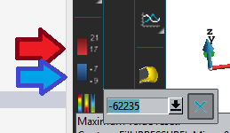
GiD will go through the Pressure result of all time-steps, i.e. will load each one of the Pressure result of each time-step, taking some time to compute the minimum and maximum Pressure value. If you already know the minimum and maximum values to set, it's recommended that you set them previously, for instance from the icon bar:
Results statistics:
To get an approximate idea of the minimum and maximum values, we can use Windows --> Create statistical results...:

This window allows the creation of several statistical results: minimum, maximum, average, accumulated, standard deviation and integral value. These statistical results are created in the last step of the analysis.
1. Create the statistical result PRESSURE//minimum and PRESSURE//maximum between steps 1.0 and 5.05.
2. Do a contour fill of PRESSURE//minimum and get the minimum value (-62,235).
3. Do a contour fill of PRESSURE//maximum and get the maximum value (22,232).
4. Use these values to fix the limits of the contour fill:
5. Do an animation.
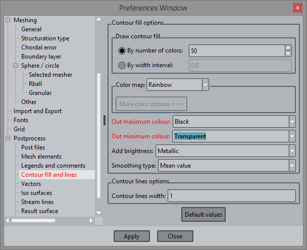
6. To check how the values outside these fixed limits are drawn, go to Preferences --> Postprocess --> Contour fill and lines:
Results for cut planes are not stored in the results cache:
Cut planes in GiD are represented in two different ways:
- implicit cuts: when the user creates a cut plane, together with the cut mesh, GiD stores interpolation information about the cut and every time the user selects a result to visualize it is interpolated to the cut plane and visualized.
- explicit cuts: when the user creates a cut plane, besides the cut mesh, GiD interpolates all results for all time-steps to the cut mesh, thus increasing its memory usage.
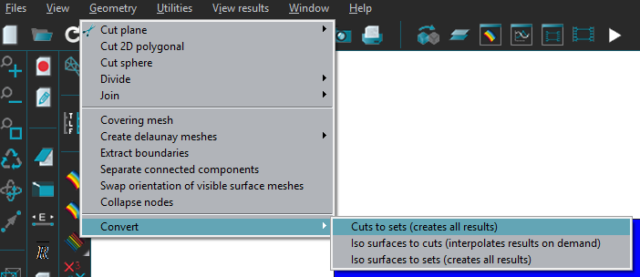
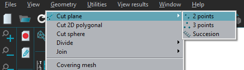
implicit cuts can always be converted to explicit cuts, using the option Geometry --> Convert --> Cuts to sets:
To automatically convert implicit cuts to explicit ones, use the preference Post-process --> Other --> Automatically convert cut to sets: (/But for this course we'll let it unchecked, read the note below)
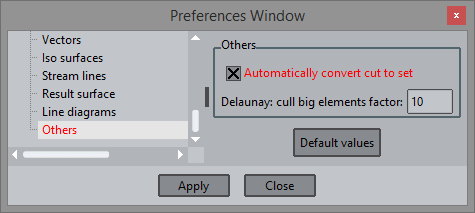
1. Check that the preference Postprocess --> Others --> Automatically convert cut to sets is disabled.
2. Check the memory GiD is using in the task manager: a around 900 MB.
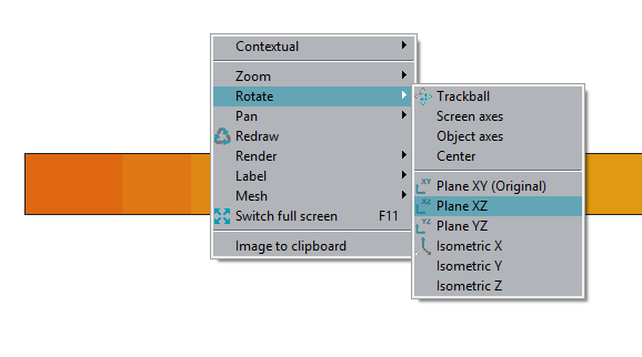
3. Do Rotate --> Plane XZ:
4. Do Cut plane --> 2 points, (after clicking the 1st point, you may press the Alt key to create a cut plane completely horizontal):
5. Animate the result from step 1 to step 27 twice.
NOTE: at the moment the use of Convert cut to sets is discouraged with Results cache enabled. Only if you increase the Results Cache Memory size to hold all results in memory you'll be able to convert cuts to sets!
Using the graphics card
This section explains how GiD can use the available graphics resources and which features can be used under the selected visualization configuration.
After explaining how GiD can use the graphics capabilities, the different drawing methods are explained and their advantages. Finally an example shows the different performance numbers with several visualization and drawing settings.
Using the graphics card: Fast/safe visualization mode
Initial GiD configuration window, when GiD is launched for the first time:
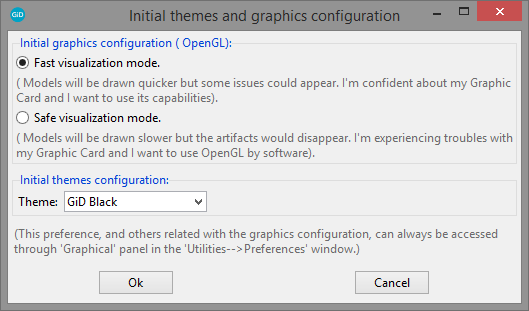
- Safe visualization mode: GiD will render the model and mesh using only the CPU, i.e. will not use hardware acceleration of the graphics card. Using this option some artifacts may disappear but models and meshes will be drawn slower. In MS Windows: the OpenGL version used is 1.1 and some features will be disabled. In Linux: this mode can also be enabled using the gidx script in a console or terminal window. The OpenGL version used is 3.0.
- Fast visualization mode: GiD will use the hardware acceleration provided by the driver and the graphics card to accelerate the visualization of the models. If some problems appear, please update your driver or use the Safe visualization mode.
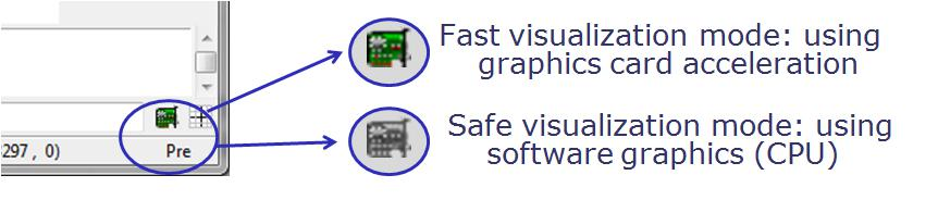
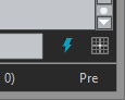
Note: when using Intel graphics with Fast visualization mode it is strongly recommended to enable the option Selection lines by software, because dynamic lines, such as the ones used when performing a zoom, creating geometries or creating cut planes, are not drawn by the Intel graphics. To check which visualization mode GiD is using you can check the card like icon on the bottom right of the main graphical window, or check the Help --> About window and pressing the About button:
Graphics mode with the Black theme:
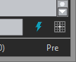
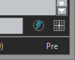
On the left, Fast visualization mode is enabled. On the right, GiD is in Safe visualization mode.
Graphics mode with the Classic theme:
This is an example of the text that appears on Help --> About --> More in Fast Visualization mode ( MS Windows): GiD internal version: 15.0 ( 64 bits) Togl 1.8: asked for an accelerated renderer, OpenGl: ... | This is an example of the text that appears on Help --> About --> More in Safe Visualization mode ( MS Windows): GiD internal version: 15.0 ( 64 bits) Togl 1.8: asked for a generic renderer, OpenGl: ... |
| This is an example of the text that appears on Help --> About --> More in Safe Visualization mode ( Linux): |
Using the graphics card: Drawing methods
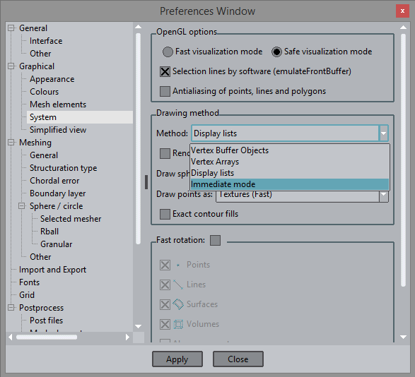
Drawing method: ( can be adjusted at Utilities --> Preferences --> Graphical --> System)
Several algorithms are used in GiD to draw meshes faster, but which rely on the underlying hardware at different levels. Faster methods needs good hardware graphics and good driver support, slower methods are safer and independent of the graphics capabilities available.
- Vertex buffer objects ( VBO): is the fastest method, but it requires OpenGL 1.5 or higher, and the Fast visualization mode. Extra memory of the graphics card is used.
- Vertex array ( VA): requires OpenGL 1.1, and can work also with Safe visualization mode too. Extra main memory is used.
- Display lists ( DL): requires OpenGL 1.0, basic acceleration if used with the Fast visualization mode. Extra memory of the graphics card is used.
- Immediate mode ( IM): requires OpenGL 1.0, is the slowest but most robust method and requires less memory than the other methods.
Summary of features available in Safe and Fast visualization modes:
Safe visualization mode | Fast visualization mode | |
Drawing: immediate mode | saves memory / slow | saves memory / slow |
Drawing: display list ( DL) | a bit faster ( uses main memory) | faster ( uses card's memory) |
Drawing: vertex array | a bit faster ( uses less memory than DL) | a bit faster ( uses main memory) |
Drawing: vertex buffer object | No ( requires OpenGL 1.5) | fastest ( uses less card's memory than DL) |
Effect: stereoscopy ( 3D) | Yes | Yes |
Effect: mirror plane | Yes | Yes |
Effect: render reflection | No ( requires OpenGL 1.3) | Yes |
Effect: shadows | No ( requires OpenGL 1.5) | Yes |
Effect: shiny contour fills | No ( requires OpenGL 1.2) | Yes |
Recommended mesh size | < 500,000 triangles | depends on the graphic's card memory available |
Using the graphics card: Example
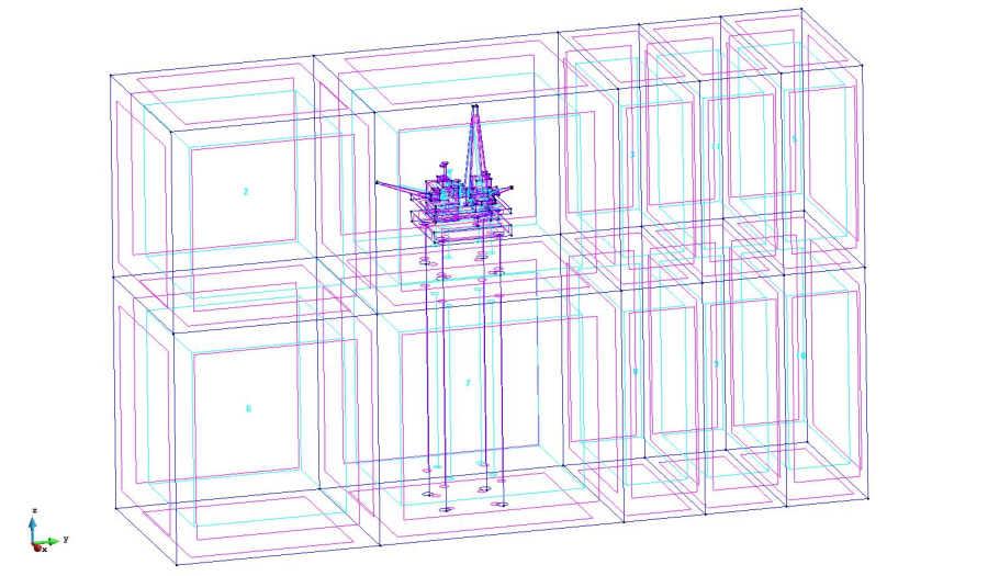
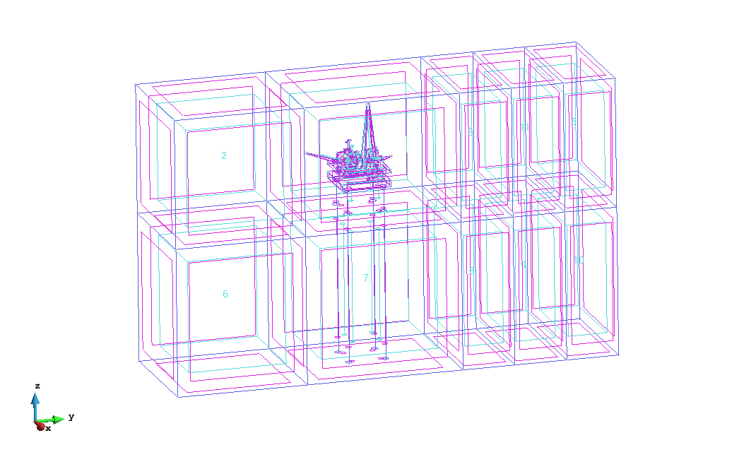
Geometry of the platform_small project.
This example is a simulation of waves against a oil platform. The model platform_small.gid can be found at Material location.
Macro creation:
1. create an empty macro, by clicking on the Record macro icon ![]() and the Stop record macro icon
and the Stop record macro icon ![]() , both on the macros toolbar. The new macro will appear on the macro's icon bar:
, both on the macros toolbar. The new macro will appear on the macro's icon bar:

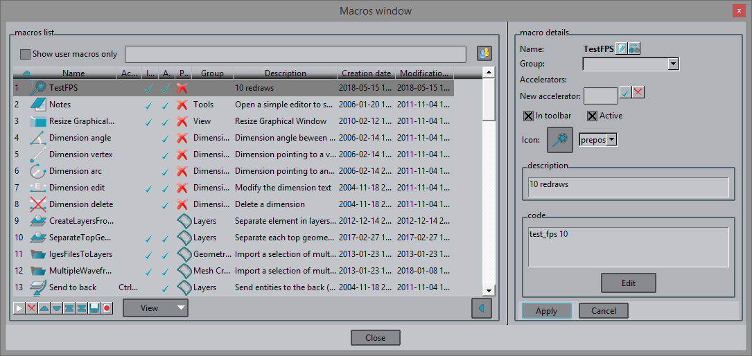
2. edit the macro with the icon ![]() on the same macros toolbar, and enter test_fps 10 in the code box:
on the same macros toolbar, and enter test_fps 10 in the code box:
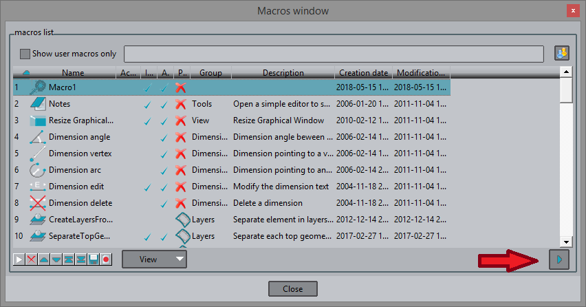
3. Edit macros window, click on the button pointed by the red arrow to expand the window and enter the code
4. load the model and test the macro, a Warning window should appear with a text like this: Redrawing 10 times ... done: 65.3 fps. ;
5. don't close this Warning window, it will be used to compare the results.
Safe Visualization mode in postprocess
1. click on the lower right card icon to change to Safe visualization mode;
2. load the model again and test the macro;
3. go to postprocess;
4. go to the preferences window and change the option Graphics --> System --> Drawing method to Immediate;
5. click on the newly created marco ( don't close the appeared Warning window);
6. go to the preferences window and change the option Graphics --> System --> Drawing method to Display lists;
7. click on the newly created marco ( don't close the appeared Warning window);
8. go to the preferences window and change the option Graphics --> System --> Drawing method to Vertex arrays;
9. click on the newly created marco ( don't close the appeared Warning window);
10. (in MS Windows with Safe Visualization mode we can't use the Vertex buffer objects drawing method).
11. in the Warning window, four lines should appear ( one for every test) with a contents like this:
| Redrawing 10 times ... done: 103 fps. <-- macro on geometry (These values are indicative and depend on the hardware used) |
Fast Visualization mode in postprocess
12. click on the lower right card icon to change to Fast visualization mode ( click no when GiD asks to save the model);
13. load the model again and click on the newly created macro ( the geometry of the model should be viewed);
14. go to postprocess;
15. go to the preferences window and change the option Graphics --> System --> Drawing method to Immediate;
16. click on the newly created marco ( don't close the appeared Warning window);
17. go to the preferences window and change the option Graphics --> System --> Drawing method to Display lists;
18. click on the newly created marco ( don't close the appeared Warning window);
19. go to the preferences window and change the option Graphics --> System --> Drawing method to Vertex arrays;
20. click on the newly created marco ( don't close the appeared Warning window);
21. go to the preferences window and change the option Graphics --> System --> Drawing method to Vertex buffer objects;
22. click on the newly created marco ( don't close the appeared Warning window);
23. in the Warning window, three lines should appear ( one for every test) with a contents like this:
Redrawing 10 times ... done: 174 fps.
Redrawing 10 times ... done: 11.1 fps.
Redrawing 10 times ... done: 41.1 fps.
Redrawing 10 times ... done: 40.4 fps.
Redrawing 10 times ... done: 45.3 fps.
(These values are indicative and depend on the hardware used)
24. compare the times obtained:
Safe visualization mode | Fast visualization mode | |
geometry | 103 fps | 174 fps |
immediate mode | 5.82 fps | 11.1 fps |
display lists | 8.95 fps | 41.1 fps |
vertex arrays | 9.98 fps | 40.4 fps |
vertex buffer objects | N/A | 45.3 fps |
(These values are indicative and depend on the hardware used)
Note: in preprocess mode the display lists drawing method is not available.
Fast rotation
Fast rotation: How it works
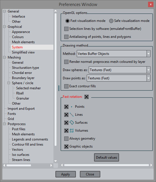
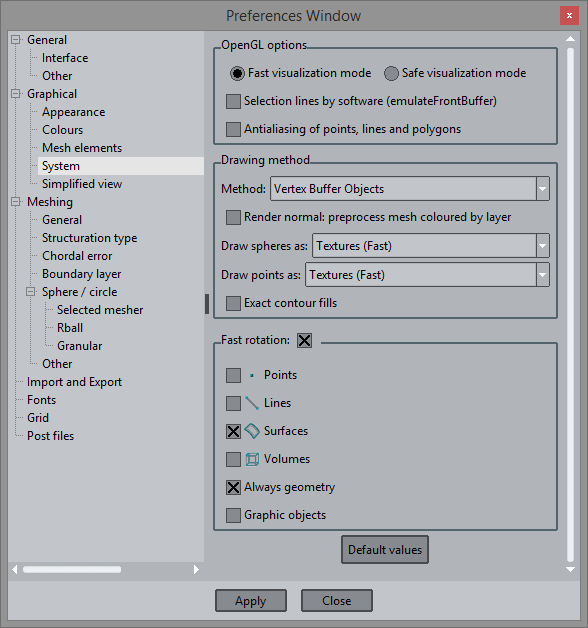
To enable this option just open the Preferences window and tgo to Graphical --> System:
When heavy models are loaded in GiD, it may last several seconds to draw a view of the model, for instance when drawing several millions of lines of a huge mesh. In these cases, it's very painful to interact with the model, i.e. rotate, zoom in-out, move it.
GiD offers a Fast rotation mode, which allows fast interaction with the model.
With this option enabled, when the user rotates the model, zoom-in or out dynamically, then GiD will change the view of the model to a simplified one, for instance instead of rotation several millions of mesh edges, only the geometry is used to rotate the model; then, when the user finished its interaction, for instance pressing the Escape button or the middle mouse button, the GiD switches back to the previous view.
Several options can be configured in Fast rotation mode: the behaviour of these depends if GiD is in preprocess or postprocess mode:
Preprocess:
- Points, Lines, Surfaces and Volumes: to draw or not to draw each type of entity when rotating.
- Always Geometry: With this option set, when you view and rotate the mesh, the geometry is drawn instead.
- Draw graphic objects: If this option is not set, when rotating the geometry, some graphical and temporal objects like normals or materials or conditions symbols are not drawn.
Postprocess:
- Lines: if it's set, when rotating the model, the boundaries lines of the mesh is drawn;
- Surfaces: if it's set, when rotating the model, a simplified view of the mesh is drawn, depending on the options set in Preferences --> Graphical --> Simplified view (please, look into the Simplified view section).
Fast rotation: Example
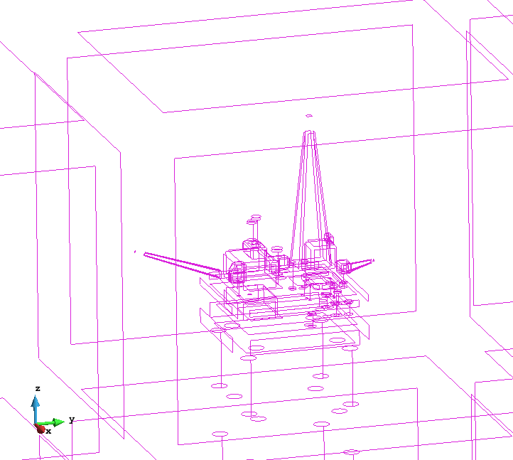
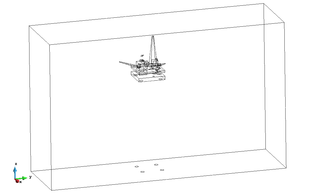
Geometry of the platform_small project.
This example is a simulation of waves against a oil platform. The model platform_small.gid can be found at Material location.
Preprocess:
1. load the model, and change to mesh view mode, using the icon  ;
;
2. open the preferences window and enable the Preferences --> Graphical --> System --> Fast rotation mode, enabling only the surfaces and with the mode Always geometry set;
3. rotate the model, use the scroll wheel of the mouse to zoom in and out and check the switching between the mesh and geometry views, and back, of the model:
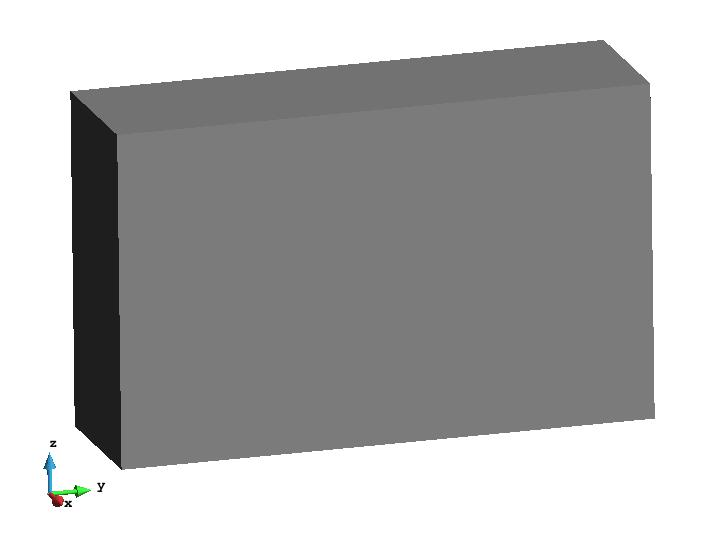
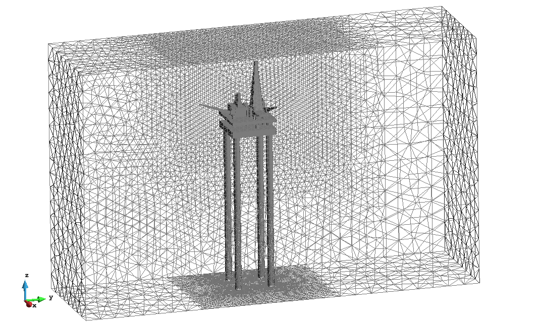
Mesh view of the platform model |
'Fast rotation' view, showing only the surfaces of the model while rotating it |

Postprocess:
4. go to postprocess;
5. enable only the Lines checkbox in the Preferences --> Graphical --> System --> Fast rotation mode section;
6. rotate the model, use the scroll wheel of the mouse to zoom in and out and check the switching between the mesh and geometry views, and back, of the model:
|
|
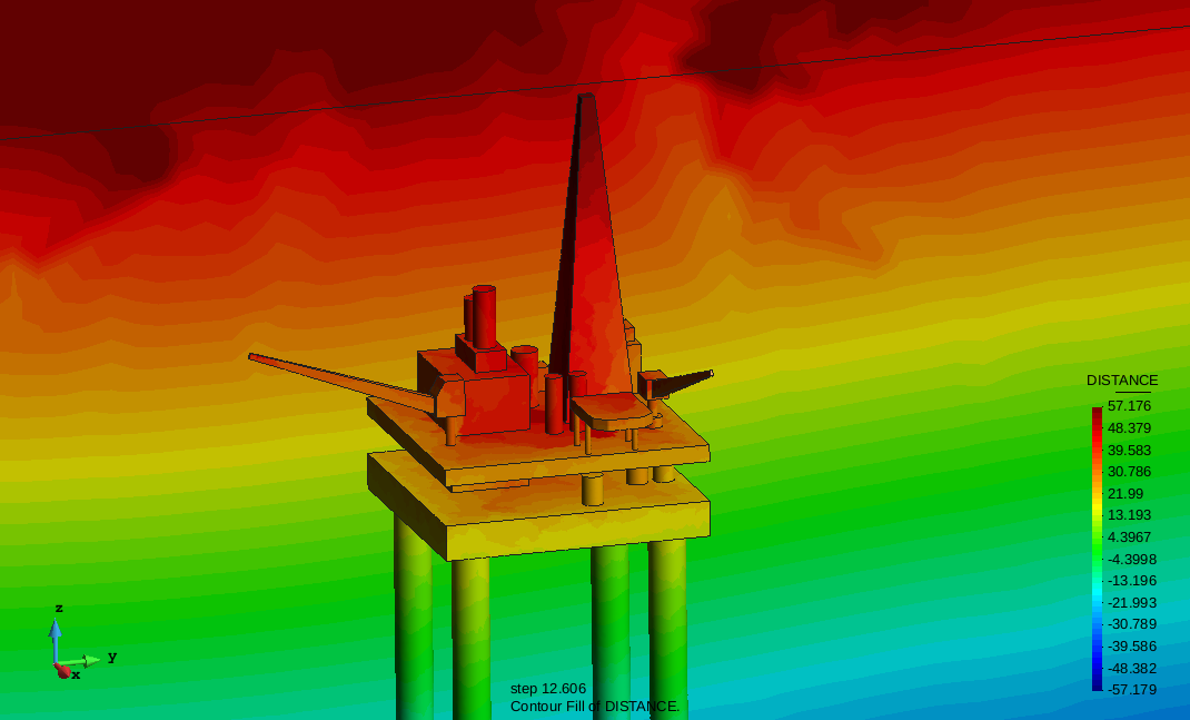
7. do a contour fill of DISTANCE (may need to change Display Style to Body or Body Boundaries);
8. do a Culling of the front faces to view the interior of the volume:

9. and zoom in to get this view:

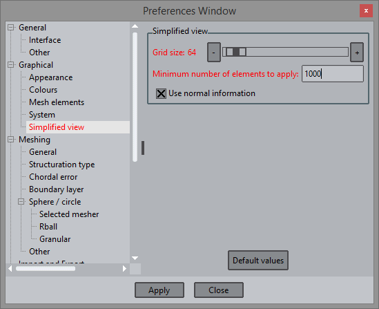
10. switch on the 'Surfaces' checkbox in the Preferences --> Graphical --> System --> Fast rotation mode section;
11. in the Preferences --> Graphical --> Simplified view section, change the Grid size to 64 and the Minimum number of elements to apply to 1000;
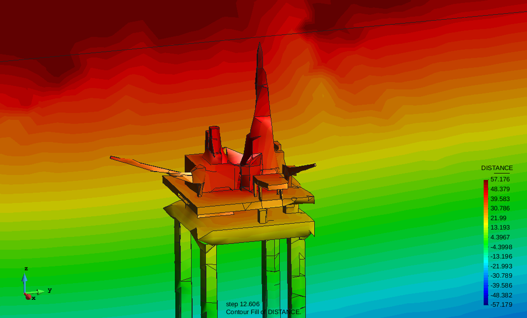
12. rotate the model, use the scroll wheel of the mouse to zoom in and out and check the switching between the mesh and geometry views, and back, of the model:
Note: When a result is displayed, the simplified view interpolates the original result into the simplified mesh. |
|
13. Now disable the fast rotation mode in the preferences window.
Simplified view
Simplified view: How it works
For huge meshes, which are very slow to draw, a simplified view can be used to speed up the interaction between the user and GiD. The operation will be performed on the original model or mesh, and only the visualization is simplified. The simplified mesh is calculated using a vertex clustering based algorithm (http://upcommons.upc.edu/pfc/handle/2099.1/20380 ) with only geometrical information. Then, each time a result is selected, it's interpolated from the original results on the simplified mesh. Simplified meshes are used if Fast rotation mode is enabled ( see Fast rotation), or at user demand using the following icons:
Toolbar: 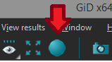 GiD is drawing the original mesh, click to change to simplified view.
Toolbar: 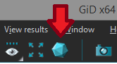 GiD is drawing using the simplified mesh, click to change to original mesh.
- Grid size: Size of the vertex clustering grid used to simplify the mesh: a smaller grid size generates a coarser mesh, a bigger grid size generates a finer mesh.
- Minimum number of elements to apply: minimum size of the mesh which will trigger the mesh simplification process. Bigger meshes will be simplified, smaller ones not.
Simplified view: Example
Geometry of the platform_small model.
This example is a simulation of waves against a oil platform. The model platform_small.gid can be found at Material location.
We'll work a little bit on the model first: from the original volume tetrahedra mesh we'll create some surface meshes to represent the platform and the surrounding box.
- load the model;
- go to postprocess;
- select the menu Geometry --> Extract boundaries;
- select All lines display style;
create a new set by selecting elements of the platform (using the Send to --> new set option of the Display style window), and change its color;

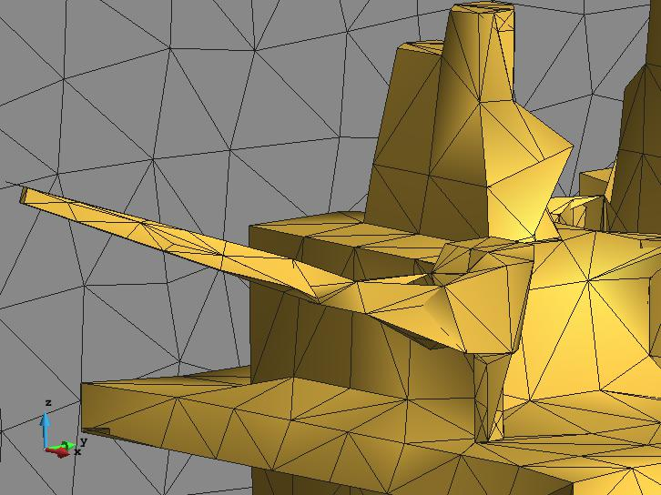
The single triangle mesh of the volume boundary has been separated in the grey box triangle set and the golden platform.
Zoom view showing the refined triangle mesh used to model the platform.- in the Preferences --> Graphical --> Simplified view section, change the Grid size to 64;
- enable the Fast draw mode by clicking on the
 icon,
icon, - the icon will change to
 , click on it to change back to the original full-detailed mesh view;
 - in the Preferences --> Graphical --> Simplified view section, change the Grid size to 640;
- enable the Fast draw mode by clicking on the
 icon,
icon, - the icon will change to
 , click on it to change back to the original full-detailed mesh view;
 - Note the difference in the details:
|
|
Visualizing particle models (DEM, PFEM, ...): Textures in spheres, circles and points
Textures in spheres: How it works
There are several ways to draw spheres, circles and points in GiD:
- Mesh (slow), using a triangle mesh to represent the sphere or point, which has between 4 and 630 triangles, depending on the detail level;
- Textures (fast): using images of already rendered spheres to speed up the drawing process, it's a compromise between quality and speed;
- Square (Fastest): the fastest way to draw spheres, use this method when speed is the most important factor.
In Preprocess these options are accessible through Preferences --> Graphical --> System inside the Drawing method box.
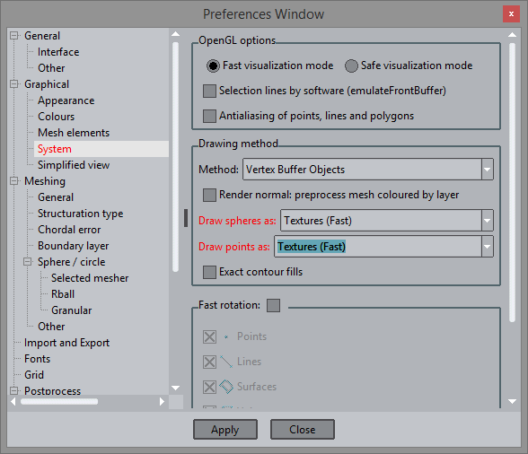 Preprocess drawing options for Points and spheres | 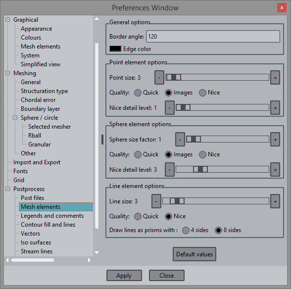 Postprocess drawing options for Points and spheres |
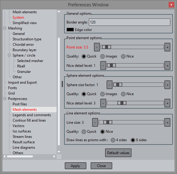
In Postprocess there are other options under Preferences --> Postprocess --> Mesh elements:
- Quick: points, spheres and circles will be drawn as big dots.
- Nice: a triangle mesh, between 4 and 630 triangles big, is used to drawn each sphere and circles for a nicer quality.
- Images: several images can be selected and will be used to draw on the point elements, using the point coordinates as the centre of the images. For a certain point, at each redraw the next image of the collection will be used.
- Nice detail level: level of detail used to draw the points, spheres and circles in Nice mode. Higher detail level will draw more triangles for each sphere or circle.
Textures in Contour Fill:
By default, a texture is also used to draw the contour fill of a result. In this case, the texture is just a color scale, like the one used to draw the legend. This option is used by default to speed-up the render of the results.
There can be interpolation problems when there are some undefined result values for some nodes.
In Preferences --> Graphical --> System the Exact contour fills options can be used to get a more accurate representation of the color bands in the contour fill result visualization, especifically in the extremes of the result scale:
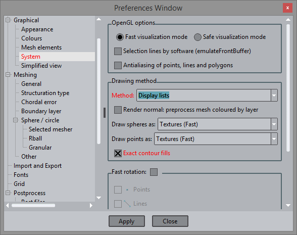
- Exact contour fills ( only with Display list and Immediate mode drawing methods, only in postprocess): if set, each element is subdivided into single color sub-elements according to the color scale, in order to get a better quality and limit representation of the color bands. This option is only available with Display lists or Immediate mode drawing methods.
Textures in spheres: Example
Geometry of the platform_small model.
This example is a simulation of waves against a oil platform. The model platform_small.gid can be found at Material location.
We will use the TestFPS macro ( test_fps 10) created in the 'Using the graphics card: Example' section.
As before (if not already done) we'll work a little bit on the model first: from the original volume tetrahedra mesh we'll create some surface meshes to represent the platform and the surrounding box.
- load the model;
- go to postprocess;
- select Geometry --> Extract boundaries;
- select All lines display style;
create a new set by selecting elements of the platform (using the Send to --> new set option of the Display style window), and change its color;
The single triangle mesh of the volume boundary has been separated in the grey box triangle set and the golden platform.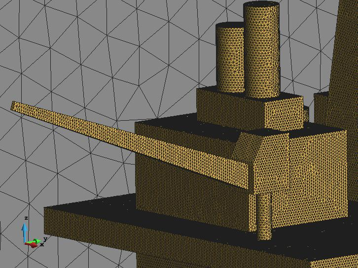
Zoom view showing the refined triangle- switch off all sets except the platform one;
- test the macro, a Warning window should appear with a text like this: Redrawing 10 times ... done: 20 fps. ;
- change the visualization style to points;
- change in Preferences --> Postprocess --> Mesh elements , change the Point elements options,to Quick; and Size to 5.5;
test the macro;
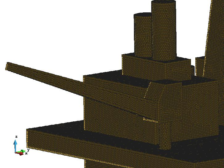
Drawing Quick points on the nodes of the platform mesh- change in Preferences --> Postprocess --> Mesh elements , change Point elements options, to Images and execute the macro;
change in Preferences --> Postprocess --> Mesh elements , change Point elements options, to Nice and set Nice detail to 5, and execute the macro;
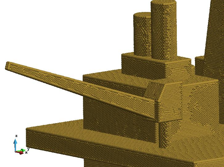
Drawing points with textures on the nodes of the platform mesh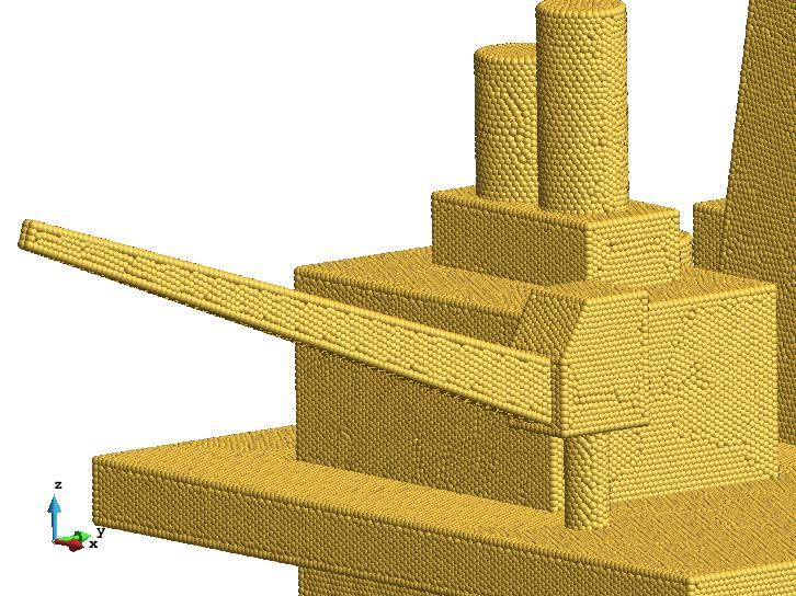
Drawing Nice points on the nodes of the platform mesh- Compare the times obtained:
Quick points: Redrawing 10 times ... done: 35.8 fps.
Images: Redrawing 10 times ... done: 18 fps.
Nice ( detail = 5): Redrawing 10 times ... done: 2.84 fps.
(These values are indicative and depend on the hardware used)
Textures in contour fill: Example
- set display style to Body Boundaries;
- Switch on the surface sets;
- set culling to front faces;
- in Preferences --> Graphical --> System change the drawing method to Display List;
- test the macro, a Warning window should appear with a text like this: Redrawing 10 times ... done: 38 fps. ;
in Preferences --> Graphical --> System enable the Exact contour fills;
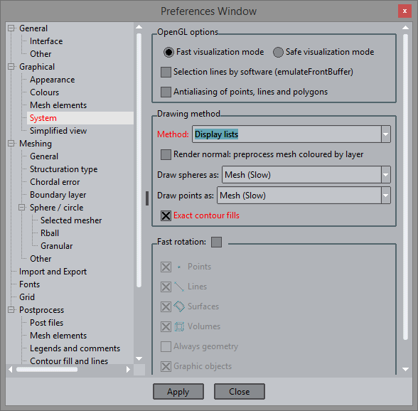
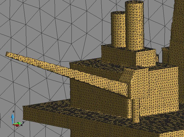
Graphical --> System preferences used in this contour fill example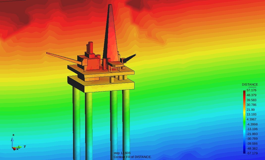
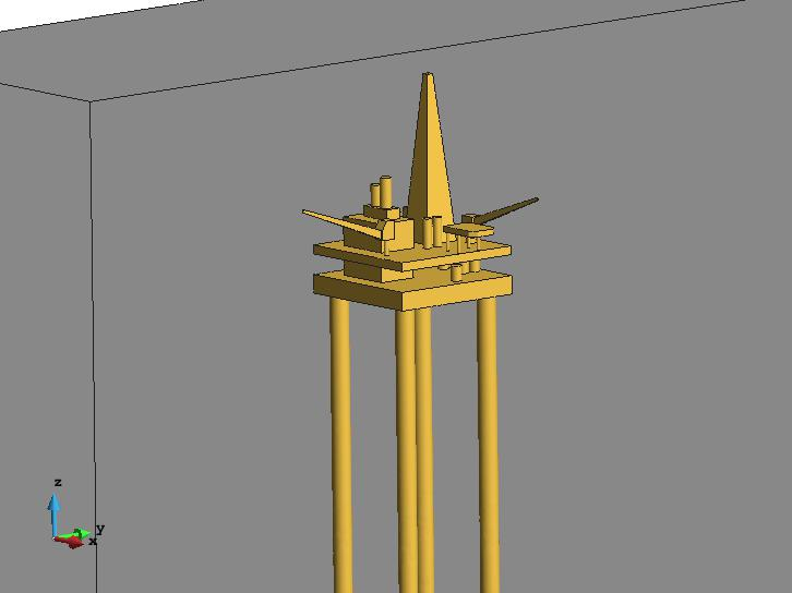
View of the model used for the contour fill test, with culling of the front faces and the two surface meshes on- do a Contour Fill of DISTANCE, and execute the macro;
- disable the Exact contour fills option in Preferences --> Graphical --> System;
- do a Contour Fill of |Velocity|, and execute the macro;
- Compare the times obtained:
Exact contour fills on: Redrawing 10 times ... done: 6.5 fps. (Exact contour fills enabled)
Exact contour fills off: Redrawing 10 times ... done: 29 fps. (Exact contour fills disabled)
(These values are indicative and depend on the hardware used)
Related content
COPYRIGHT © 2022 · GID · CIMNE