GiD - The personal pre and post processor
Geometry creation and edition
- Enrique Escolano
- Abel Coll Sans
- Adrià Melendo
Description
This tutorial is focused in the use of the basic geometric tools of GiD.
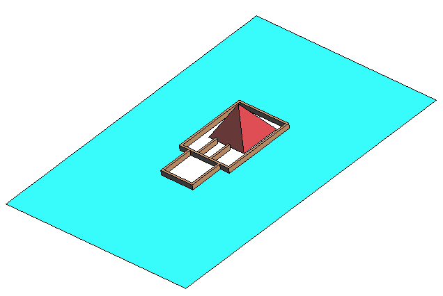
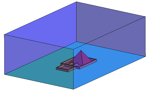
We will explain how to create a CAD model of the Egyptian construction shown in the figure below.
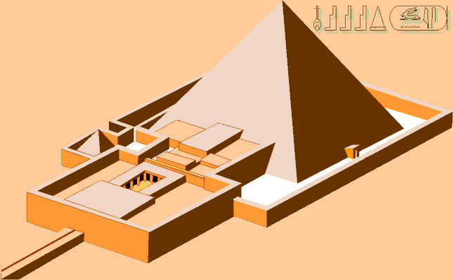
Egyptian funerary complex perspective
Some simplifications of the geometry are allowed. In the following parts of the course some schemes describe the dimensions of the simplified shape of the model.
We want to create a volume of a portion of the air around a control volume. We use a 300x200x100 m box so that the faces of the box are relatively distant from the temple (the creation of this model is supposed to be used for a CFD simulation analysis of the airflow around the building).
Simplified model
In this section we will use the GiD facilities (creation of lines, surfaces, copy tool, use of layers, etc.) to create the geometry of the Egyptian construction shown following scheme (dimensions are in meters). The width of all the walls is 2 meters.
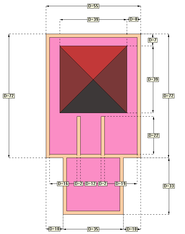
Plant scheme 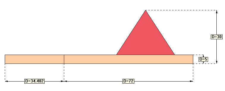
Profile scheme
Of course, there is not a single way to build this shape. We will use several tools in this course which may not be the optimal ones, considering that the objective is to show as more tools as possible for the geometry creation using GiD.
NOTE: Not all dimensions are specified in the scheme, the undetermined ones should be approximated based on the images.
Points and lines creation
We will start creating the wall lines located on the ground (plane z=0)
To facilitate visualization and selection tasks we will separate entities in several layers with this tree structure:
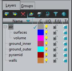
Final layers structure.
We will start creating the lines of the plant, in the z=0 plane.
Be sure the layer in use is the 'walls' one. The layer in use is marked with a 'check' between the name and the color of the layer. To set the 'walls' layer as the layer in use just double click onto the name of the layer.
New entities will be created in the current 'layer to use'.
Line creation
- Choose the Line option, by going to Geometry->Create->Straight line or by going to the GiD Toolbox (the GiD Toolbar is a window containing the icons for the most frequently executed operations. For information on a particular tool, click on the corresponding icon with the right mouse button).
- Enter the coordinates of the beginning and end points of the auxiliary line. The coordinates of a point may be entered on the command line either with a space or a comma between them (but not both). If the Z coordinate is not entered, it is considered 0 by default. After entering the coordinates of one point, press Return. Another option for entering a point is using the Coordinates Window, found in Utilities->Tools->Coordinates window...
For our example our coordinated origin will be set at the lower-left of the bounding box of the building, and we will create the lower line that starts at x=10 and ends at x=10+35=45 units, the coordinates are then (10,0) and (45,0) respectively. Besides creating a straight line, this operation implies creating the end points of the line.
Write then:
- 10,0<Return>
- 45,0<Return>
- Press <Esc> twice to indicate that the process of creating the line is finished. (Pressing the <Esc> key is equivalent to pressing the center mouse button).
- If the entire line does not appear on the screen, use the Zoom Frame option, which is located in the GiD Toolbar and in Zoom option in the mouse menu.
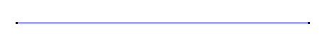
Creating a straight line
NOTE: When creating a line, after clicking the first point, you can press the Alt key to snap the dynamic line to the screen horizontal, vertical or 45º diagonals.
NOTE: The Undo option, located in Utilities->Undo, enables you to undo the most recent operations. When this option is selected, a window appears in which all the operations to be undone can be selected.
Join NoJoin option
When generating geometry, very often it is needed to select some point: a new one (like the ones that have been defined in the previous steps for defining the lines), or an existing one. When an already existing point is wanted to be selected, user must go to Contextual->Join Ctrl-a in the mouse menu (right-click), or pressing <Ctrl>+a.
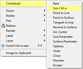
Contextual menu when expecting a point
The pointer will become a square, which means that you may click an existing point. User can change alternatively between both modes (clicking an existing point or a new one) in the same selection process.
- Choose the Line option, by going to Geometry->Create->Straight line or by going to the GiD Toolbar.
- Press <Ctrl>+a to select an existing point (ensure the mouse pointer is square-like)
- Click on the point on the left.
- Press <Ctrl>+a again to select now new points (ensure the mouse pointer is now a cross)
- Then enter the following points by coordinates (like in the previous steps):
- 10,33
- 0,33
- Press <Esc> twice to indicate that the process of creating lines is finished.
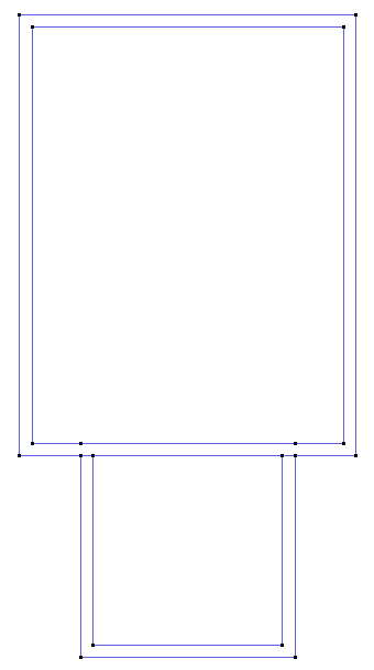
Now the model should look like the figure.
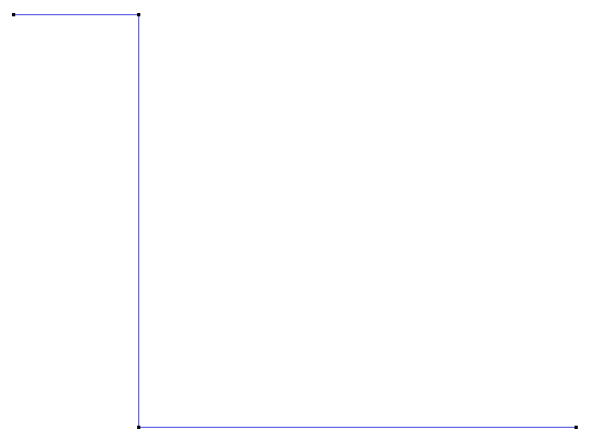
State of the model geometry at this point.
Relative coordinates
In GiD there are two ways of defining the coordinates of a point: absolutely (like all the coordinates we have entered since now in this course) or relatively to the last point entered (using @ symbol). We will now enter a point using this second option, which is very useful when points wants to be entered knowing some distance.
- Choose the Line option, by going to Geometry->Create->Straight line or by going to the GiD Toolbar.
- Press <Ctrl>+a to select an existing point (ensure the mouse pointer is square-like), and select the point which is more at the left in the model.
- Press <Ctrl>+a to select a new point (ensure the mouse pointer is a cross).
- Enter the following relative coordinates: (@0,72)
- Press <Esc> two times to leave the line creation mode.
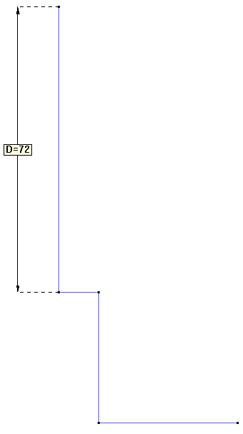
Line created with a length of 72 meters, entered as a relative coordinate to its second point.
As it can be appreciated, the new point has been created at 72 meters (as the relative coordinates indicated) of distance from the first selected.
Copy tool
Another useful option for creation of geometry is using the different geometrical transformations GiD offer in the Copy and Move windows.
Now we are going to copy the upper point translated 55 m in x direction, and creating a line between the source and destination point by extrusion.
- Use the Copy window, which is located in Utilities->Copy (you can access that window also using the
 icon from the Toolbar, or the keys <Ctrl-Shift-C>).
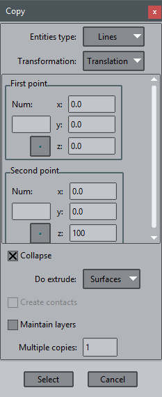
 - Within the Copy menu and from among the Transformation possibilities, select Translation. The type of entity to receive the translation is a line, so from the Entities type menu, choose Points.
- We want to make a translation of 55 units in the x direction, so we should leave the coordinates of the First Point at (0,0,0), and set the coordinates of the Second point at (55,0,0) (the translation is defined with the relative vector from the first to the second point)
- Do extrude: set to Lines
- The following options of the window should be the same as the ones in the figure.
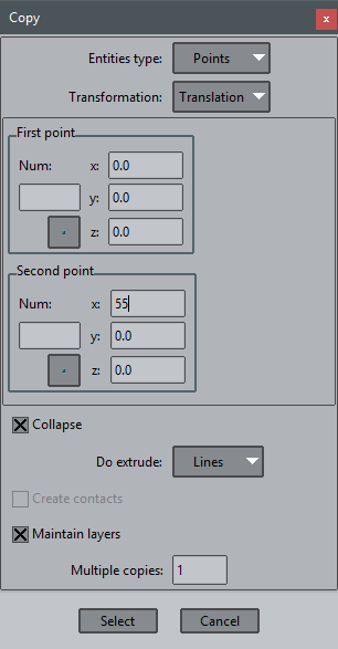
Copy options to be used.
- Click on Select and select the point to be copied (the upper-left point)
- Press <Esc> to exit the selection mode.
You would get the model like the one shown in next figure.
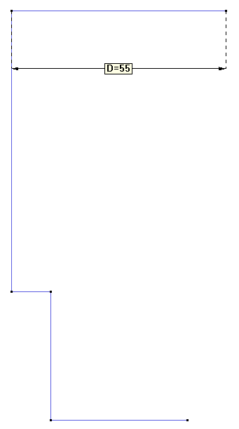
State of the model at this point.
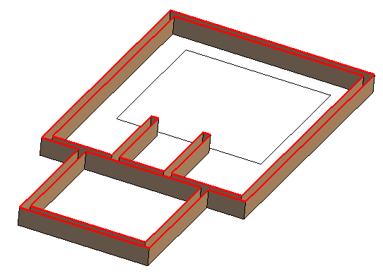
With the copy tool we can create the lines on the right with a copy by symmetry, around an axis on x=27.5.
Set Entities type to be selected as Lines, Transformation as Mirror
Check Two dimensions to define the symmetry only with two points on the axis (instead of the 3D case that require three points on the symmetry plane)
Set two axis points, like (27.5, 0.0, 0.0) and (27.5, 1.0, 0.0), Do extrude: No and check that Collapse is marked
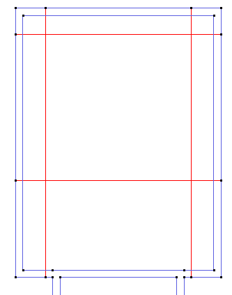
and select the three red lines to be copied.

Copy lines by symmetry.
Finally create another line to split the shape in two rectangles
Offset
The walls have a width of 2 meters, now we will build the inner perimeter using the Copy tool with 'Offset'.
And now we will orient all curves of the upper rectangle coherently (e.g. all clockwise or all counter-clockwise), to be able to do a copy by offset.
use: Utilities->Swap normals->Lines->Select
And select all lines, then are drawn an arrow in cyan, representing the curve tangent, and a pink arrow representing the normal (defined for 2D planar curves only, rotating tangent 90 degrees to the left, around the z axis).
Click the lines to be swapped to point all pink arrows inside the upper rectangle
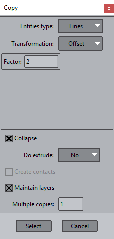
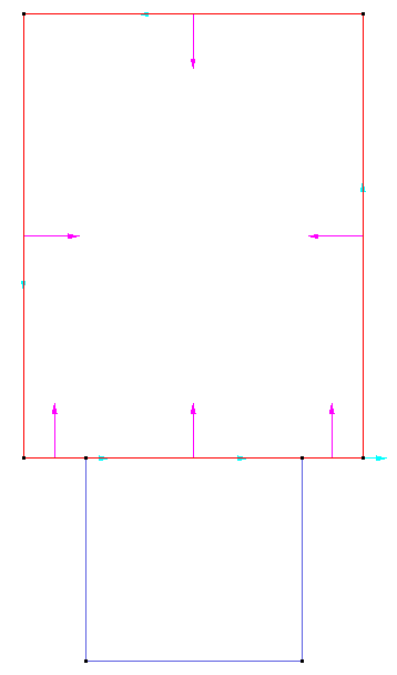
The offset factor is positive pointing to the line normals direction, or negative in the opposite one. When selecting the lines to be copied we see its orientation. We can cancel the copy deselecting all before finish (can do it with "Clear selection" of the contextual menu)
Repeat the operation for the lower rectangle, obtaining this result
Inner perimeter created by two offsets.
Intersection
To create the square of the pyramid we know the distances to the boundary, we can use the copy by translation to create some auxiliary lines, and then intersect them with
Geometry->Edit->Intersection->Lines
And then delete the unwanted lines.
Geometry->Delete->Lines
then in the contextual menu (right-mouse button) select Lower Entities to delete also the points that become isolated after the deletion.
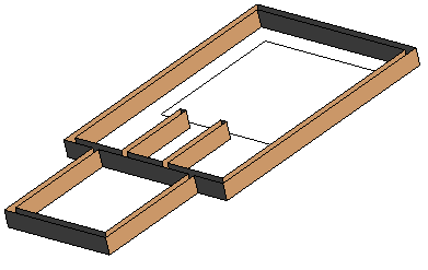
Finalize the lines creation
Now you should complete the remaining geometry until obtaining a figure similar to the one shown below. Use the explained geometrical operations to complete by you own the geometrical definition of it.
It may be useful for you to use some other geometrical operations, like the ones present in Geometry menu. They are easy to use, and its names are intended to be self-explicative, we encourage you to try some of them for the creation of the geometry (e.g. division, intersection of lines, deletion, collapse of points, etc.)
A new tool will be need to obtain final result, if there are two lines connecting tangent, you can use Geometry->Edit->Join->Lines to obtain an unique line without middle point
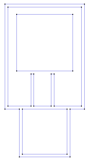
Current state of the model.
Take care of all lines of the model, check that the walls are totally connected without any division.
Surface creation
In the following sections we are going to complete the geometrical model definition using different surface creation techniques.
Extrusion of walls
For creating the walls we will use the translation tool inside Copy window for the extrusion of the lateral surfaces, and then create the top surfaces.
First of all let's use the Rotate function (Rotate->Trackball from the mouse right button menu, or clicking the corresponding icon ![]() ) to see the lines of the model from a different point of view, which will help us to understand the model.
) to see the lines of the model from a different point of view, which will help us to understand the model.
Ensure the active layer is the one named 'walls' and follow the next steps:
- Open the Copy window, which is located in Utilities->Copy (you can access that window also using the icon from the Toolbar).
- We are going to apply a translation of 5 units in z direction to all the lines except the ones of the square defining the base of the pyramid. For this purpose ensure all the options of the window are like the ones shown in the figure.

Options to be applied
Select the lines of shown in left figure and click on Finish button. The result should be like shown in the figure on the right.
Take care on the different visualization modes that can be used for visualizing the geometry. This options are Normal, Flat and Smooth, and can be selected from the Render option in the mouse right button menu.
Note: in Flat render mode surfaces are painted with the layer color. Don't worry if you are seeing different colors, layer colors could be changed.Creation of top of walls
Now we have created the lateral surfaces of the walls, and we must create the top surface.
We have all the contour lines of the surfaces to be created, so we have several options of creating them. The simplest one is to select Geometry->Create->NURBS surface->By contour (or clicking the corresponding icon), and select all the contour lines which define the contour of the surface.
We need to select as boundary all curves on z=5, an easy way to select them is to set an appropiated view, like Rotate->Plane XZ
then select with a box all upper lines, and unselect with another box the unwanted vertical curves.
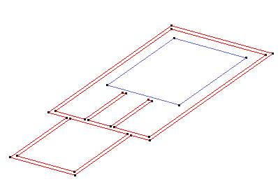
The lines to select to create the top planar surface
Creation of the pyramid
We are going to create the pyramid in the layer named 'pyramid', so you have to set this layer as the one in use.
For creating the pyramid, first of all we need to create the vertex of it, and need to calculate its coordinates. You know that the total height of the pyramid is 30 meters, but you don't know the x,y coordinates of the projection on the ground. You can calculate it as the midpoint between two diagonal points.
Open the calculator with
Utilities->Tools->Calculator...
| Select the More...->Get point and click a corner of a diagonal (top left) |
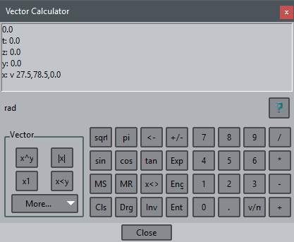
- Select Geometry->Create->Point and modify in the command line the coordinates changing z=0 to z=30, to obtain: 27.5,78.5,30.0 and press enter to create the point with this coordinates
Note that the points can only be seen in Render Normal (not in Flat or Smooth mode).
- Then create one straight line from each vertex of the quadrilateral base of the pyramid to the vertex of the pyramid.
For creating the lateral surfaces of the pyramid:
- Select Geometry->Create->NURBS surface->By contour (or click the corresponding icon), select the three lines of one face of the pyramid and press <Esc>.
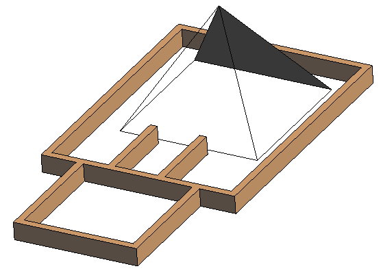
Manual creation of a surface of the pyramid
For simple geometry configurations, GiD can detect the contour lines of a possible surface automatically. We will use this option.
Select again Geometry->Create->NURBS surface->By contour. But now click on the right mouse button and select Search in the Contextual menu.
Then click once for example the lines of the base of the pyramid (a line of the desired surface)
As you can see, each time you click a line, GiD find automatically the other lines which close a surface parting from the selected line.
Creation of ground surface
We should define the limits of the domain into where the simulation will be done. This limits should be far enough from the model to avoid the effect of the boundary conditions in the results.
We are going to create now the surface of the ground of 200x300 m.
- Set the 'ground_outer' layer as the one in use.
- Create a rectangular surface: Geometry->Create->Object->Rectangle
with a corner at (-70,-100,0) and the opposite corner at relative coordinates (@200,300,0). Then, we will add a hole to this surface using
Geometry->Edit->Hole surface->With lines
then select the surface to be holed and then select the trimming lines
The rectangle holed
Then Set the 'ground_inner' layer as the one in use and create the other missing surfaces of the ground.
Creation of the 'ground_inner' surfaces
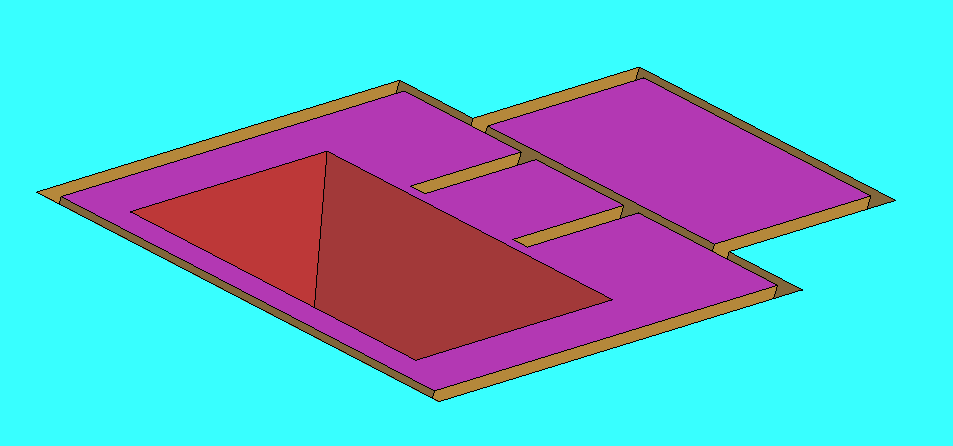
You should obtain the following geometry, seen from below in the figure:
Creation of control volume surfaces
For creating the outer surfaces of the control volume we will use again the Translation tool of the Copy window.
- Set the 'air//surfaces' layer as the one in use.
- Open the Copy window, which is located in Utilities->Copy, and set all the values of the parameters as the ones shown in the following figure. Note that the 'Maintain layers' checkbutton is unset, to create the new entities in the current layer to use instead of the layer of its source entity.
Parameters to be used for the extrusion of the outer lines of ground surface.
- Select the 4 outer lines of the ground surface and press Finish.
Now the lateral surfaces of the control volume have been created.
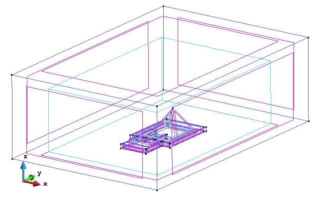
- Create the top surface of the control volume by its boundary lines, and the model should be like the one shown in the figure.
State of the model creation at this point.
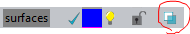
Note that you can apply transparency to one Layer by clicking in the icon placed on the right part of the corresponding layer in the Layer Window.
Volume creation
Due to the hierarchical definition of the geometry inside GiD, a volume requires to have a closed path of surfaces as contour. For checking that a path of surfaces is water-tight (closed), GiD offers one graphical tool (Higher entities) which is very useful.
- Click on View->Higher entities->Lines. You should obtain the information of how many surfaces own each line. In this case all the values should be 2, like is shown in next figure.
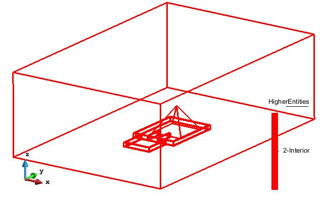
Higher entities of the lines of the model.
Press <Esc> to return to the normal render mode. The last step for the geometry creation of this model is create the volume:
- Select Geometry->Create->Volume->By contour and select all the surfaces of the model except the upper rectangle (simulating an user selection error).
Then a window like this is shown (the number of entities could be different depending on the way of create the geometry).
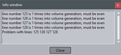
Lines of the surface missing to close a volume
The meaning of this 'ugly message' is that the volume is not closing topologically in the printed entities. You can use copy/paste of the last list of line ids "125 126 127 128" to set on its labels and identify visually the problem.
View->Label->Selected->Lines 125 126 127 128 and you will see that just are the lines of the missing surface.
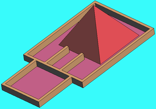
- Repeat the creation of the volume, but now selecting all surfaces, then press ESC, and the volume should be created. Note that the volume (using GiD Normal render mode) is represented by a light blue line following the contour lines.
Now the geometrical model is finished, and it should look like the one presented in the figure.
Geometrical model finished.
Save this gid project with Files->Save as.. with the name 'Pyramid_geometry'
It is recommended to try to generate a coarse mesh to be sure that all is ok and they are not geometric problems for a future simulation.
E.g. use Mesh->Generate mesh... with a general meshing size=20 m, you must obtain a mesh with only tetrahedra elements.
Related content
COPYRIGHT © 2022 · GID · CIMNE