GiD - The personal pre and post processor
Basic GiD management
The objective of this course is to get familiarized with GiD: how to change the views of the model, how to manage the layers, and other basic features. Some of these features are both in the preprocessing and the postprocessing modes of GiD, although the examples shown are from the preprocessing one.
Many times the text will make reference to 'entities'. Almost all the options explained in this course are valid both for geometrical and mesh entities, although the examples used are often geometrical ones.
User interface
Starting GiD
When GiD is started for the first time a pop-up appears where you can choose OpenGL working mode and GiD theme.
If you are confident with your graphic card please choose Fast visualization mode. With this mode the model will be drawn quicker, so you will feel a better interaction with the model. Nevertheless, some issues could appear depending on your graphic card and its drivers.
These courses have been done with the GiD black theme. The theme only affects the GUI appearance, so there is no problem to follow the course with another theme.
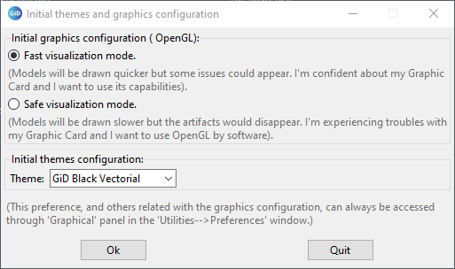
These two options can be changed later in the preferences window (select Utilities->Preferences).
Change OpenGL option
This option is managed inside Utilities→Preferences... Graphical->System branch.
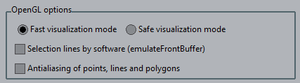
Also it's possible to change it by clicking on  /
/  in the bottom right corner of GiD window.
Change theme
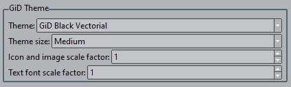
User can choose between different themes (i.e. Classic, Black Vectorial,...), which change drastically the GUI appearance. User can also choose between some icon sizes in each theme.
These options can be changed in GiD Theme option inside Utilities→Preferences... Graphical->Appearance branch.
Preprocessing and Postprocessing modes
GiD basically works in two modes: preprocessing and postprocessing.
To change between both modes please select Files->Postprocess or Files->Preprocess (or clicking  /
/  in the main toolbar).
Warnline
In some of the operations made in GiD, GiD gives information about what is expected to do by the user. This information is very useful the first times GiD is used as a guideline for the user.
The place were this kind of information is shown is the lower part of its main window.

Command line
Using GiD, sometimes the user is asked to introduce data with the keyboard. The 'Command line' must be used for this purpose. It is placed in the lower part of GiD window.

Status bar
The Status & Information bar located at lower part of GiD's Window, provides basic information at a quick glance.

From left to right you can find:
- Zoom factor
- Current number of nodes and elements (Click to access to Status Window)
- Current renter mode (Click to change render)
- Number of layers in Pre, number of sets in Post
- Mouse coordinates (Click to open "Coordinate window" in Pre and "Change result units" in Post)
- Current Mode: Pre or Post
Mouse menu
Clicking the right mouse button on the main graphical window opens an on-screen menu with some visualization options. To select one of them, use the left or right mouse button; to quit, left-click anywhere outside the menu.
The first option in this menu is called Contextual. You can select from different options relevant to the function currently being used, e.g. when asking for a point they appear options like "Point in line", to select a point over a line, or "Arc center" to select the coordinates of the center of an arc.
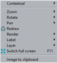
- Zoom, Rotate, Pan, Redraw and Render are the same options as in pre and postprocess mode.
- Label in preprocess shows a label with the current entity number, depending if we are in preprocess, geometry and mesh, or in postprocess.
- Layer/Mesh (depending if we are in pre or postprocess mode) menu lets user to switch on/off layers.
- Switch full screen changes GiD main window to full screen mode.
- Image to clipboard creates an image fo the current visualization and placed in the clipboard.
Escape function
An important thing a GiD user should know as a general philosophy of use of the program is the Escape key functionality: in almost all the actions performed by the user, to declare the action as done the user should press Escape key (or press the center mouse button).
Change views of the model
In the View menu user can find the options to change the point of view in which the model is shown. Many of these options are also accessible by the right mouse button menu, or the icons toolbar.
Zoom
To zoom in or out the model user can choose the corresponding options in the Zoom section of the View menu or the right mouse button menu.
A user friendly way of zooming the model is to use the wheel of the mouse, or clicking the center button of the mouse while the Shift key is pressed.
To get a view which includes the whole model the Frame option must be selected.
The icons corresponding the zoom operations are the following ones:
Zoom in: 
Zoom out: 
Zoom frame: 
Pan
To move the view of the model user must select the option Pan. This option is accessible from the View menu, the right mouse button menu, or moving the mouse while the Shift key and the right mouse button are pressed.
The corresponding icon for the pan option is the following one: 
Rotate
In View->Rotate menu (also present in the right mouse button menu) there are the options to rotate the view of the model.
A user friendly way of rotating is to move the mouse while its left button and the Shift key are pressed.
The corresponding icon for rotating the model is the following one: 
Set center of rotation
An interesting option for rotating the view of the model is to set the center of rotation. To change it:
- Select View->Rotate->Center from top menu or Rotate->Center from right button mouse menu. Then, the cursor changes into the selection mode.
- Select an existing point of the model.
- Now rotate the model and check that the center of the rotation is the one selected.
View management
There are several pre-loaded views in order to align the object axes with the screen axes. These views can also be selected clicking on  icon.
icon.
When we are working it's possible to change to previous views using 
 icons.
It's also possible to save in a file an specific view to use it later in order to take some snapshots of our model. In order to do that select View->View->Save... and to read it just select View->View->Read...
This option is useful to get the same perspective of the same model when we work on different sessions.
Render modes
In the View menu user can find the Render options. They are also accessible from the right mouse button and the status bar.
- Select View->Render->Normal
- Select View->Render->Flat
- Select View->Render->Smooth
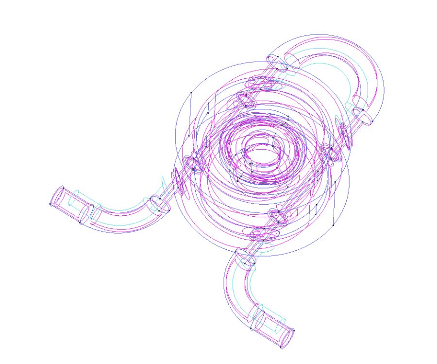
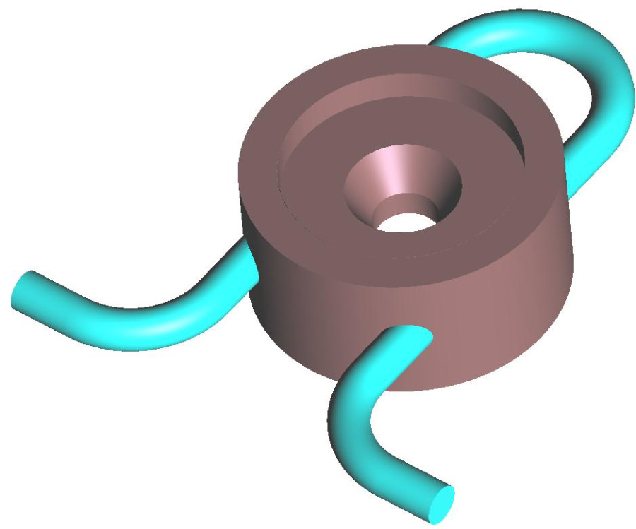
In Normal render mode, user can see the entities drawn in different colors, depending on the kind of entity: volumes in light blue, surfaces in pink, lines in blue, and points in black.
Flat render mode draws each geometrical entity using the color of the layer it belongs to, and Smooth mode uses also this criterion, but lines are not drawn to represent the geometry in a smoother way. The following figure shows the visualization of the model changing render modes:
|
|
Creating images
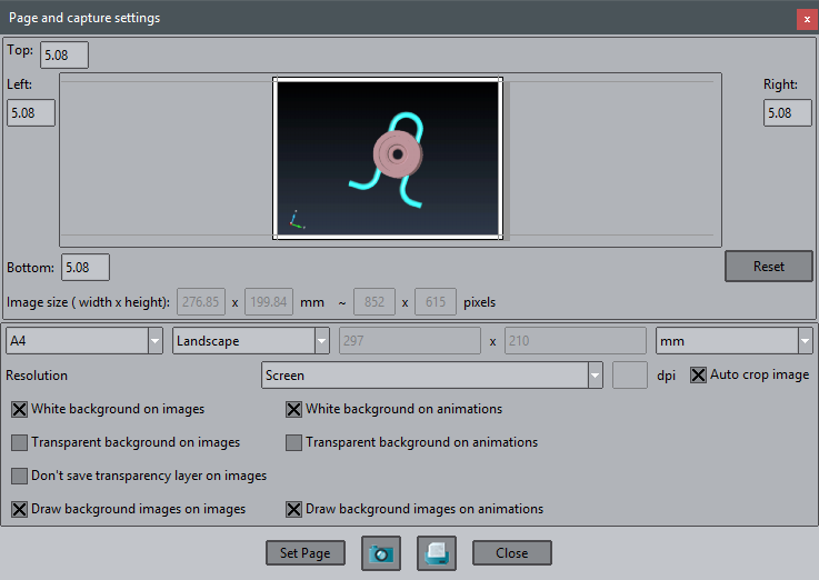
We can take snapshots of our model. You can save images in several formats. The properties of the image (resolution, size, etc.) can be assigned in Page and capture settings option.
- Select Files->Page and capture settings...
- Check the Auto crop image option in order to cut the image in the model limits
- Click on Set Page button
- Click on Close button
In order to save the image with the defined properties in Page and capture settings:
- Select Files->Print to file and the desired image format through the menu bar
- Choose the location where you want to save the image
- Choose a name for the file
- Click on Save button
NOTE: This action could also be done by clicking on  through the icon bar. This icon can also be found in the "Page and capture settings" window. In this case the image format is chosen while saving the file in the "Files of type" combo-box.
Preprocessing mode
Load a model
In the Files menu user can find the typical operations for managing the GiD projects like save a project, open an existing project, import and export files, print or quit the program. Most of this options are also accessible from the icons toolbar. The corresponding icon is shown in the menu, next to the option.
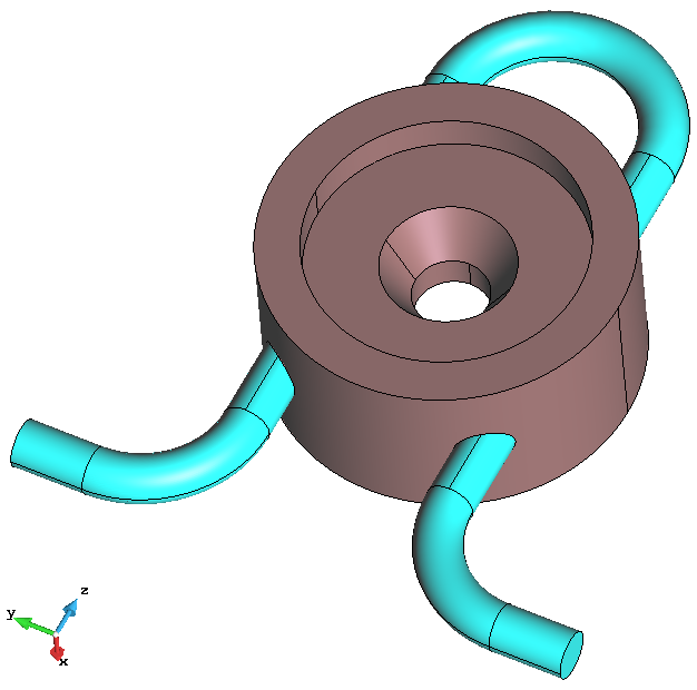
- Click on Files->Open... and select the GiD model gid_model_basic_course.gid. GiD also can load a model just with drag & drop. The following model should be loaded:
Geometry and Mesh modes
In the preprocessing part of GiD there are two basic modes the user can work with: geometry and mesh. Just in order to see how the mode can be changed we are going to generate a mesh with all the default parameters.
- Select Mesh->Generate mesh... The following window should appear.
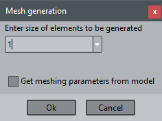
- Click OK and wait for the mesh generation. Once the mesh is generated, a window pops up and show the user the result from the mesh generation.
- Click on 'View mesh' option, and the following visualization of the model should appear:
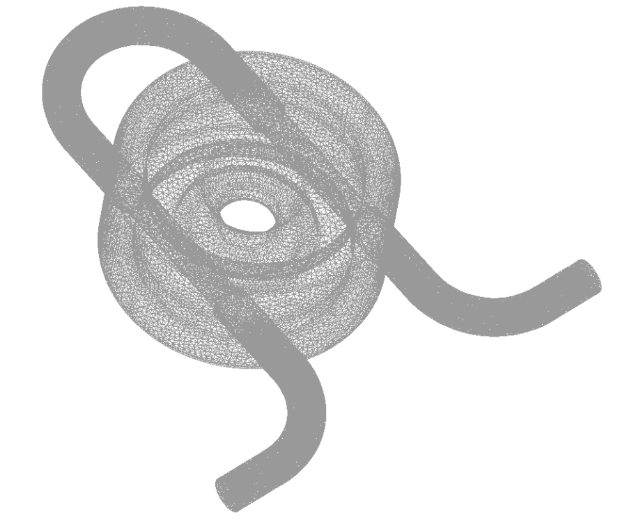
Now we are in 'mesh' mode. Changing the render mode user can see that the color of the mesh entities also follows the Layer colors.
Selecting View->Mode->Geometry user can change to the geometry mode again. The  icon in the toolbar switch between both modes.
Entities information
Labels
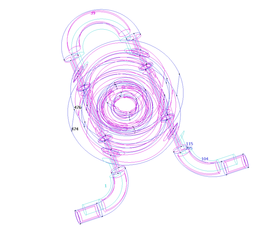
Using the option Labels present in the View menu (and also in the right mouse button menu), user can see the number of the entities of the model. Either for points, lines, surfaces or volumes user can choose between viewing the numbers of all the entities, or just the selected ones.
In the following figure the model can be seen with the number of some entities:
List entities
User have also the option of viewing all the characteristics of a specific entity by selecting List in the Utilities menu (or clicking  in the icons toolbar).
For example:
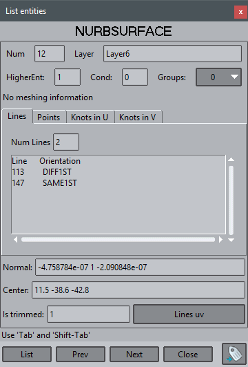
- Select Utilities->List->Surfaces in the top menu
- Select some surfaces of the model
- Press Escape
An example of the information got using this option is the following figure:
Signal
In complex geometrical models sometimes it is hard to localize an specific entity. Using the Signal option in the Utilities menu user can know graphically where the entity is, as GiD shows with a red lines cross its position. This option is also present in postprocessing mode.
As an example we will signal the line number 290:
- . Selec Utilities->Signal->Lines
- . Write in the Command bar the number 290 and press ENTER. The result is shown in the next figure:
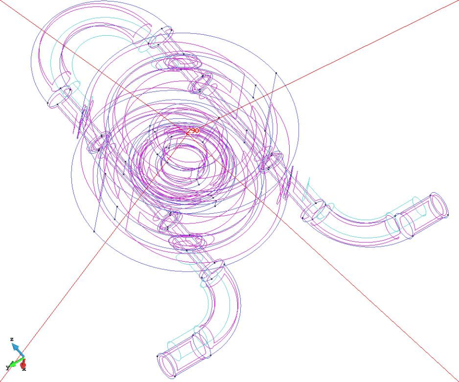
The red lines are centered always onto the specific entity independently on the rotations or view movements.
Layers and groups
A really useful way for organizing the different parts of the model is using 'Layers'.
Open the Layers window by selecting the Utilities->Layer and groups option or clicking  in the upper icons toolbar. The following window should raise up:
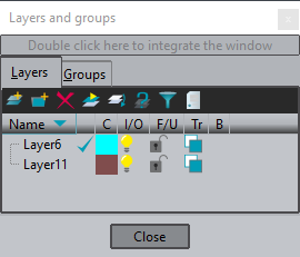
As it can be read in the upper part of the window, if user double click on that part, the Layers window is integrated in GiD window. User can choose to work with the Layers and groups window integrated or not inside the main GiD window.
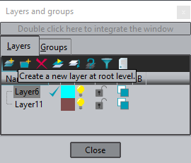
All the actions related with layers and groups can be accessed by clicking on the right mouse button in the Layers and groups window. Most of them can also be used by the corresponding icon at the upper part of the Layers window.
By moving the mouse over the icons located at the upper part of the window and staying 2 seconds onto an icon, a help message is shown in order to give the user information about the action associated with the icon.
Create a layer
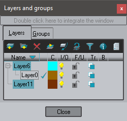
GiD allows a hierarchical structure of Layers, so as a Layer can contain sub-layers. Let's create a Layer into another one as an example:
- Select (using the left button of the mouse) the 'Layer6'.
- Select the New child option in the right mouse button menu, or click
 in the upper part of the Layers and groups window. Automatically, a layer named 'Layer0' should appear, as shown in the following figure:
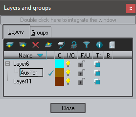
Rename a layer
To rename a Layer user should select the layer in the Layers and groups window and press F2 key, or select the Rename option in the right mouse button menu.
- Select the Layer0
- Rename it to 'Auxiliar'
Now the Layers window should look like the following picture:
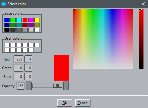
Change the color of a layer
By clicking on the colored square next to each layer name, the following window pops-up, allowing the user to change the color of the layer:
Send entities to a layer
User can send entities to a specific layer. As an example we are going to send to the layer 'Auxiliar' a part of the model:
- Select the layer 'Auxiliar' in the Layers window
- Select the option Send to from the right mouse button (or click
 icon)
icon) - Select All and select the volume shown in red in the following figure:
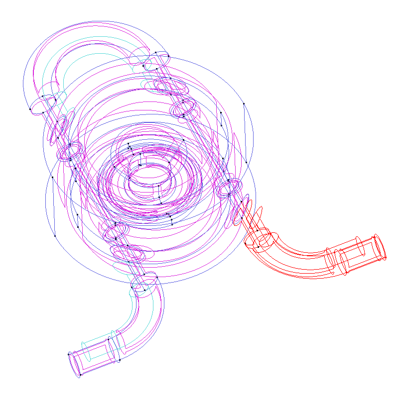
- Then press Escape to exit the selection mode.
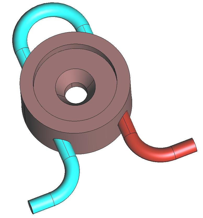
- Set the render mode to Flat. The color of selected volume has changed to the one of the layer 'Auxiliar', as shown in the following figure:
Switch on/off
By clicking on the  icon which is next to each Layer inside the Layers and groups window, user can switch on and off the corresponding layer. This is very useful in order to visualize just some specific parts of the model.
Freeze a layer
At the right side of the bulb, user can set an icon which is a lock  . If the lock is closed
  , the layer is frozen. If a layer is frozen, GiD won't apply anything to the entities of that layer. For instance, if user select some entities to be deleted, if they are into a frozen layer they won't be erased.
Transparency
Next to the 'lock' icon of each layer is the transparency icon ![]() . By clicking there, the user can set a layer to be transparent or not. The following figure shows the model with the Layer11 set as transparent:
. By clicking there, the user can set a layer to be transparent or not. The following figure shows the model with the Layer11 set as transparent:
Postprocessing mode
Load results
There are two ways to load the results simulation information into GiD:
- If the model has been calculated inside GiD, and so the results are inside a GiD project, then just loading the GiD project and the changing to postprocess mode is enough. This can be achieved clicking on this icon: , or selecting the Files->Postprocess menu entry.
- If only a mesh and results file(s) is present then GiD should be started, and switched to postprocess mode before loading the file(s).
In this case we will use the first option.
- Switch to postprocess mode: or Files->Postprocess
Entities information
Labels
Using the option Label present in the View menu (and also in the right mouse button menu), user can see the number of the entities of the model. Either for nodes, elements or results user can choose between viewing the numbers of all the entities, or just the selected ones.
List entities
User have also the option of viewing all the characteristics of a specific entity by selecting List in the Utilities menu (or clicking in the icons toolbar).
For example:
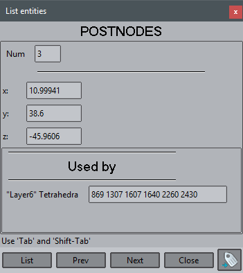
- Select Utilities->List->Nodes in the top menu
- Select some nodes of the model
- Press Escape
An example of the information got using this option is the following figure:
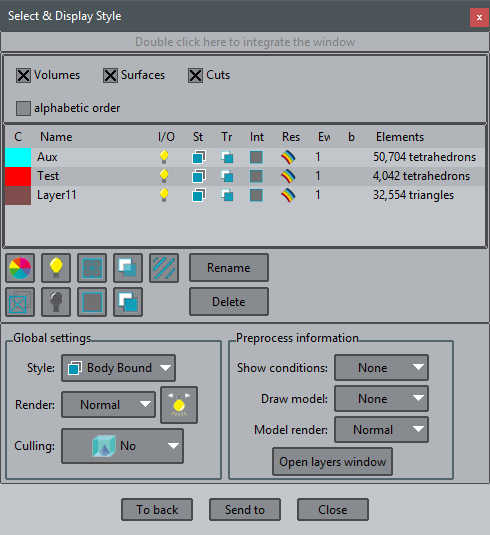
Select and display style
Through the Select & Display Style window several options can be specified for the different sets (containing volumes, surfaces or cuts). Among these options, sets can be switched on and off, their color properties can be changed, and their transparency too.
Other interesting options which can be changed are the style of the set and the width of the elements' edges.
From this window, volumes, surfaces or cuts can be deleted or their names can be modified.
The Select & Display Style window can be integrated inside GiD interface, just double click on the upper bar of the window. To tear it off again, double click the upper bar again.
- Select Window->View style... using the menu bar or clicking on
Rename a layer
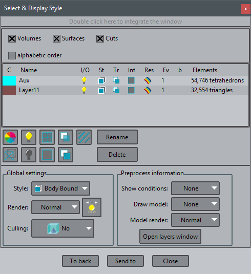
To rename a layer user should select the layer in the Select and display window and press F2 key, or press the Rename button.
- Select the Layer6
- Rename it to Aux
Now the Layers window should look like the following picture:
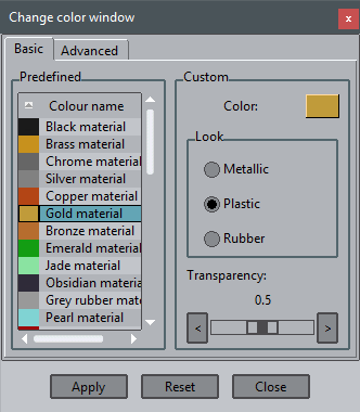
Change the color of a layer
By clicking on the colored square next to each layer name, the following window pops-up, allowing the user to change the color of the layer:
Send entities to a layer
User can send entities to a specific layer. As an example we are going to send to the layer 'Test' a part of the model:
Our model only has 2 layer. We will create a new layer with some elements.
- Press button Send to, and select New set
- Select some elements
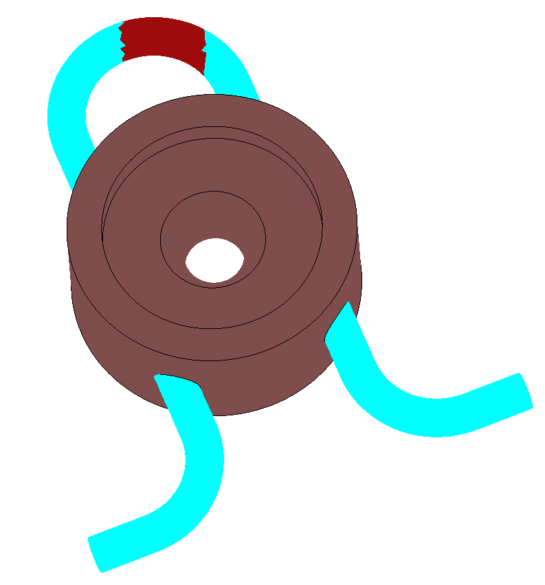
- Select some elements
- Press Escape
- A window appears asking for a name. Enter 'Test'
- Press Accept
A new layer is created with the selected elements. Now we can change the color of the new layer.
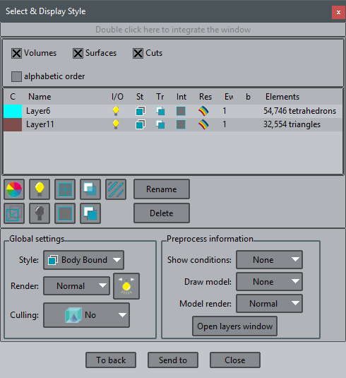
Switch on/off
By clicking on theicon which is next to each layer inside the Select and display window, user can switch on and off the corresponding layer. This is very useful in order to visualize just some specific parts of the model.
Style and transparency
By selecting one set and clicking on one corresponding style icon at the St column or clicking on  , the style for the selected mesh is changed. Bear in mind that a boundary visualization of the surface of a sphere nothing will be visualized, as a sphere surface has no sharp borders.
Mesh styles can also be changed clicking on the icon , placed in the left icon bar. This style affects all sets of the model.
Next to the style icon of each layer is the transparency icon ![]() . By clicking there, the user can set a layer to be transparent or not.
. By clicking there, the user can set a layer to be transparent or not.
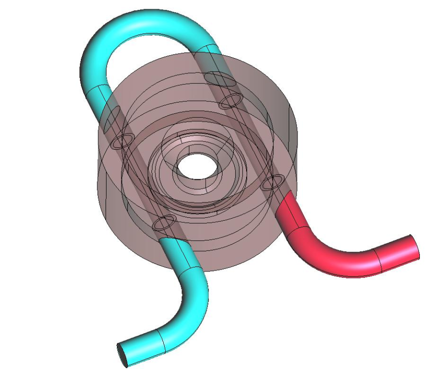
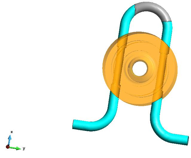
- Select Layer11 and change the style to Body
- Set it to transparent
The model should look like this:
COPYRIGHT © 2022 · GID · CIMNE